¶ Introduction and Usage
Thank you for chosing the Emonio P3 !
This product allows you to measure and record the energy consumption of electrical devices and systems quickly, easily and accurately.
The energy platform of the company Emonio GmbH (https://pro.emonio.de) offers the ability to record the measurement data historically, to combine several devices or to generate mathematical and statistical analyses. In case you need an account to access above platform, please visit our shop at: https://shop.emonio.de .
The Emonio P3 is suitable to:
- Measure and display the electrical quantities in the range of over-voltage Category III
- Measuring three voltages to neutral
- Measuring three currents by means of split-core transformer or Rogowski coil
- Measuring the active, apparent and reactive power of three one-phase consumers or one three-phase consumer
- Measuring the grid frequency
- Determination of the power factor
- Recording the measured data in the internal memory
- Transmitting the data via WiFi to an energy management system
The instrument may not be operated while being open. Measurements in damp areas or under adverse environmental conditions (wet or high humidity, dust, combustible gases, vapours or solvents) are not permitted. Other adverse conditions are thunderstorms or storm conditions such as strong electrostatic fields, etc.
Using the device under circumstances as described above, may cause damage to the measuring instrument, there is also the risk of short circuit, fire or electric shock.
For measuring only test leads and accessories that are tailored to the specifications of the instrument (minimum: CAT III, 300V) are to be used.
The meter must not be modified. The safety instructions must be observed!
¶ Safety Notes
¶ Symbols used:
| Symbol | Description | Symbol | Description |
 |
Warning of dangerous voltage. Risk of electric shock ! |
 |
Warning, danger ! |
 |
Complies with EU directives. |
 |
Double or reinforced insulation |
 |
Do not dispose in household trash. |
 |
Reboot, activate Access Point (AP) |
 |
WiFi |
 |
Operating condition |
 |
Alternating current |
 |
Fuse |
Please read the entire manual before using the device, it contains important informations about the correct and safe operation. Damage to property or personal injury caused by improper handling or failure to observe these safety instructions will void the warranty / guarantee and there is no liability. For further damages we do not accept liability!
The Emonio may only be connected by a specialist. Consult a professional if you have any doubt about operation, safety or connection of the device. The security of the system in which the meter is integrated, is under the responsibility of the installer. Measuring instruments and accessories are not toys and must be kept out of childrens' reach.
Use only with accessories certified for over-voltage category III, 300V. The use of fully insulated accessories, guarded against accidental contact are absolutely necessary for connection to the neutral conductor! If the neutral line is disconnected from the supply during operation, the full supply voltage of the phase A (10) will be on the neutral line (9). The use of a magnetic probe tip or other not fully insulated accessories on the neutral line (9) is a great danger!
In commercial institutions, the accident prevention regulations of the professional association for electrical systems and equipment must be observed.
The voltage between the three phases (10), (11) and (12) and the neutral line (9) must not exceed 264V ~. The voltage between the three phases (10), (11) and (12) must not exceed 440V ~.
The voltage at the current inputs (5), (6) and (7) must not exceed 1V ~.
Be especially careful when connecting the test leads. The touch of electric lines is dangerous!
Before each use the meter and all peripheral components (test leads, test adapters, power converters) should be checked for damage. Do not attempt any measurements if the protecting insulation is defective (torn or demolished). Do not use the meter immediately prior to, during or after a thunderstorm (lightning / over-voltage). Make sure that during the measurement hands, shoes, clothing, the floor, switches and switching components are dry.
Avoid operation in the immediate vicinity of strong magnetic or electric fields and transmitting antennas or RF generators because the measured values can be falsified.
The device is only to be installed in interior rooms with max. pollution degree of 2.
Never immediately turn on the meter when it was moved from a cold to a warm room. The resulting condensation could destroy the device under certain circumstances. Allow the unit to reach room temperature slowly.
If it is suspected that safe operation of the instrument is no longer possible, the device must be taken out of service and secured against inadvertent operation. It can be assumed that safe operation is no longer possible if:
- apparatus comprising visible damage
- the device no longer works
- It was stored under unfavourable conditions for a longer period
- stress caused by transport
Exercise extreme caution when fitting the current transformers and measuring lines (5 to 7 and 9 to 12). There is a risk of electric shock ! Use of protective equipment (eg.: insulating gloves, shoes, goggles, etc.) to prevent electric shocks and arcs is strongly advised.
In schools and training centres, hobby and self-help workshops, handling of measuring instruments must be supervised by trained personnel.
If possible try to avoid working alone so that assistance can be made in case of emergency.
¶ Product Description
The Emonio measures current and voltage values by means of the connected current transformer and test leads. The consumed active, apparent and reactive power is calculated and transmitted every second via WiFi to the measuring platform. There, the data is stored and can be analysed, combined, averaged and graphically displayed using different dashboards.
Alternatively (in the absence of an Internet connection) the data will be stored as a CSV-file in the built-in 8MB large Flash memory for later processing. An SD card adapter (Emonio X1) is available as an accessory, which increases the recording time to more than a year even if recording interval is set to 1 second.
You have the possibility to transfer the internally stored CSV file periodically via SMTP or FTP. Alternatively you can upload the file to a configured energy platform via Telemetry export.
The interaction with the meter takes place predominantly via WiFi and web browser or via App (BLE).
¶ What's included
- Measurement device “Emonio P3”
- Four measuring lines (blue, brown, black, grey) 0.75m or 1m, min. CAT III, 300V
- Three split-core current transformers: YHDC, type: SCT-010 with +/- 0.33V output*
- Three magnetic test tips 6.6mm, black: Electro PJP, type: 606MG6,6-IEC3IV-0
- One alligator clip, blue: Cliff FCR7943, CAT III, 300V
- Magnetic foil on Backside (for mounting on e.g. the door of a distribution board)
- 3mm grommet
- User manual
- Transport case
* Alternatively you can order Rogowski coils with diameters of 25mm to 150mm to measure currents from 2A to max. 4700A.
¶ Operating Elements
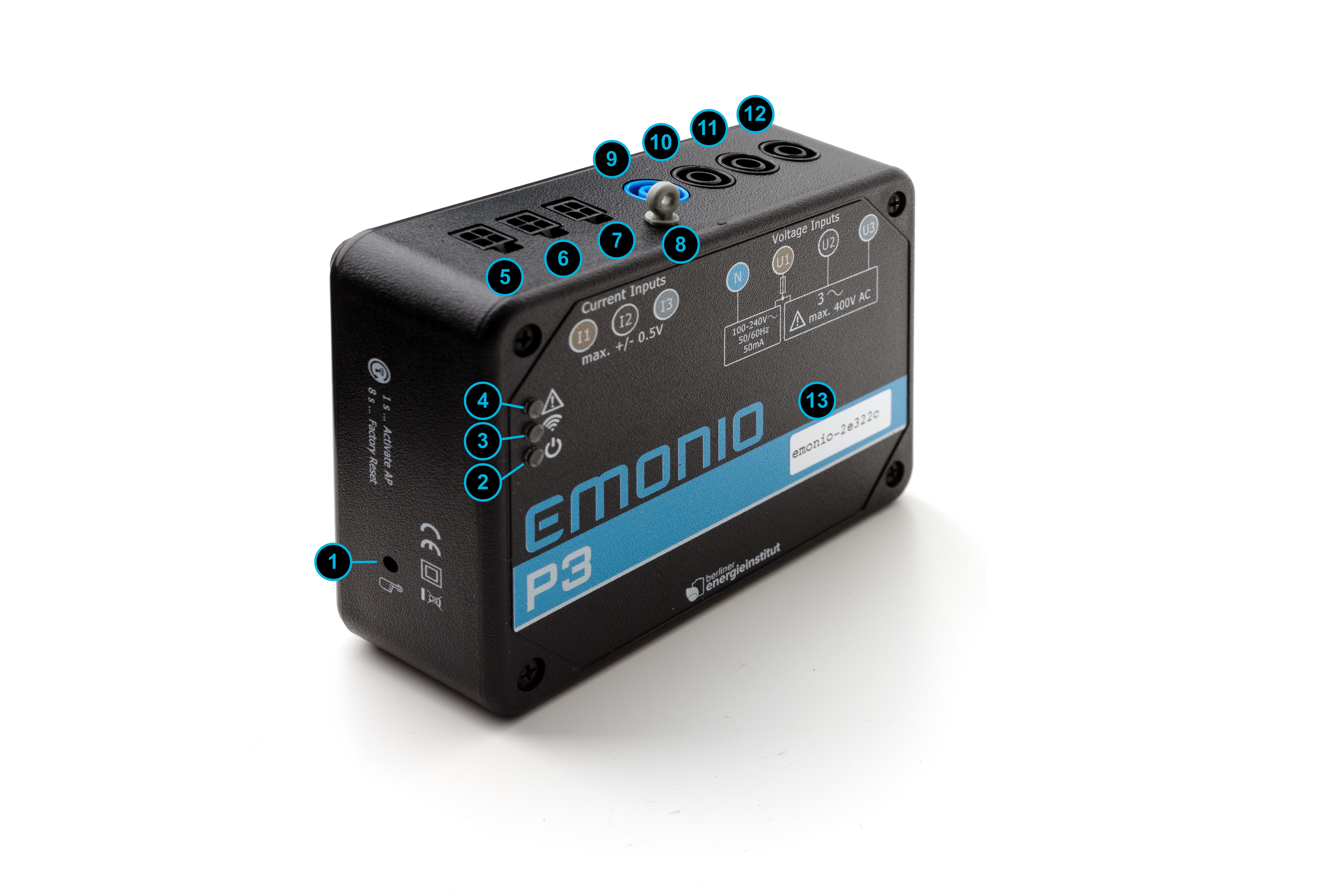
- Button ‘activate AP / factory reset’
- Status-LED ‘Power’
- Status-LED ‘WiFi’
- Status-LED ‘Error’
- Current input for Phase A
- Current input for Phase B
- Current input for Phase C
- Grommet for mounting
- Test lead for neutral line
- Test lead for Phase A
- Test lead for Phase B
- Test lead for Phase C
- Device-ID
¶ Status LEDs
|
Power LED (green) (2) |
Significance |
|---|---|
|
off |
Not connected to power (Neutral line and Phase A) or internal fuse triggered. |
|
fast flashing |
Initial configuration needed (no admin-password has been set yet). |
|
on, occulting every two seconds |
Status: ok. Normal operation. |
|
WiFi LED (yellow) (3) |
Significance |
|---|---|
|
off |
WLAN, AccessPoint inactive. |
|
on |
AccessPoint is active. |
|
short flash |
WLAN-connection active, data is successfully transmitted. The frequency of the flashes shows the data transmission. This is to be configured in Setup/Telemetry. |
|
fast blinking |
No WiFi connection possible (wrong SSID, password or the chosen WiFi network cannot be reached) |
|
slow blinking |
WiFi connection successful, but no connection to telemetry server (wrong server-URL, password, port, etc.) |
|
rapid flickering |
Factory Reset will be performed, if the button is released now. Device will reboot. |
|
Error LED (red) (4) |
Significance |
|---|---|
|
off |
No error. Normal operation. |
|
fast blinking |
General error. See website and chapter 12 for details. |
|
slow blinking |
Warning. For details see website. Or (temporary): firmware is being installed right now. |
|
rapid flickering |
The complete configuration will be erased if the button is released now. The Telemetry-token, the kWh-counters and the CSV-files will not be deleted. Device will reboot. |
¶ Button
|
Button WiFi / Reset (1) |
Function |
|---|---|
|
short press (ca. 1 sec.) |
Start or stop internal Access Point (AP). |
|
hold for 8 seconds |
Reset configuration to factory defaults. As soon as the green LED flickers, the button can be released. The factory reset has been executed and the device will restart. Counter values and CSV-files will not be deleted. After reset to factory defaults, the Emonio has to be reconfigured and an admin-name and password has to be set! The following settings will be reset:
|
| hold for ca. 15 seconds |
All configuration will be erased if the button is released while the red LED is flickering. Device will reboot. The Telemetry-Token, the kWh-counters and the CSV files will not be deleted ! |
¶ Site Requirements
This instrument has been designed for use indoors. Operation is safe under the following ambient conditions: max. 2000m above sea level, ambient temperature of 5° C to 40° C, maximum relative humidity of 80%. Max. variation of the supply voltage of +/- 10%. The installation site should be clean and free of dust (pollution degree 2).
¶ Connection to Power Supply
The power supply of the measuring device is established using measuring lines (9) and (10). It is recommended to always connect the neutral line (9) first and remove last.
¶ Internal Fuse
The internal power supply is protected with a fuse. Should the device be connected to excessive voltage, the fuse will be triggered and must be replaced.
To replace the fuse first make sure to disconnect all external accessories and cables from the device. Remove the four screws on the front plate and the front cover. Replace the fuse with one of the same type that is: 250mA, FA, IR >= 10kA (e.g. Mersen G084002).
It is of utmost importance that the fuse is of the ULTRA-FAST acting type ! ("FF" or “FA”). - If a common (fast) fuse is used, the varistor will be damaged or even worse, the whole device can be permanently damaged !
¶ Installation with residual-current Devices
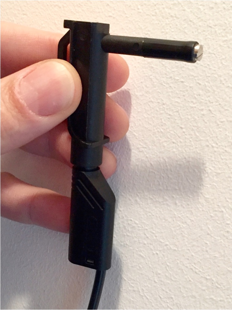
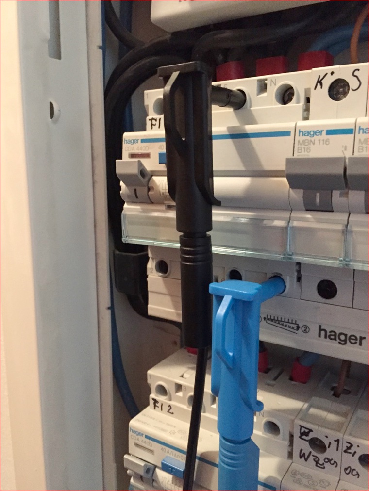
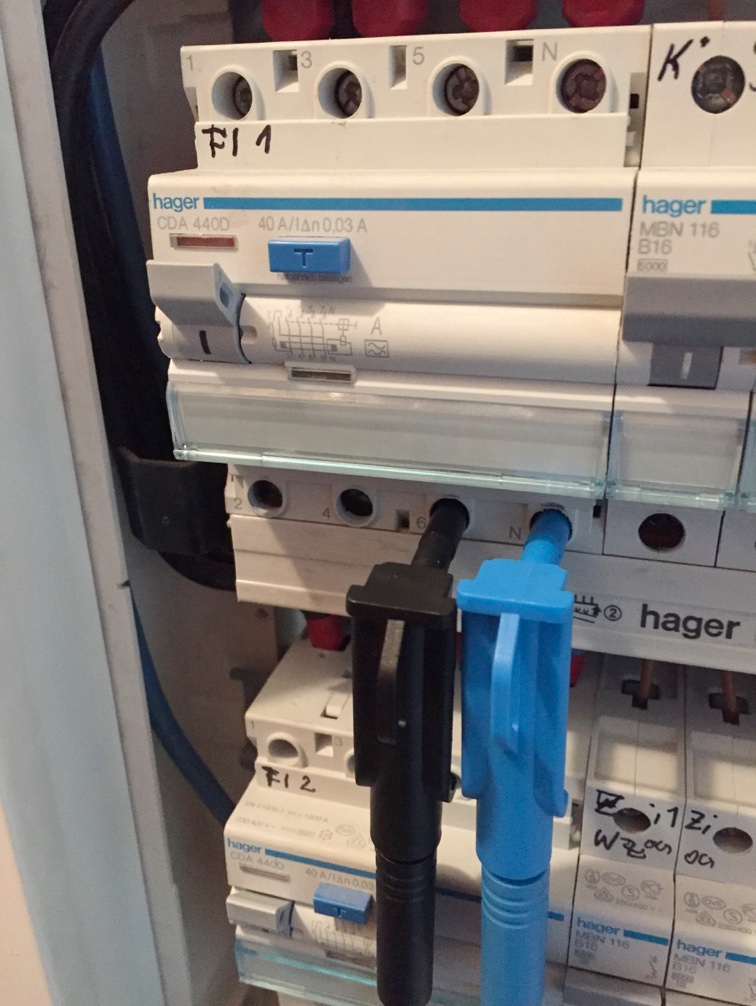
The cables for the phase A (10) and neutral conductor (9) provide current to the integrated power supply. These connections must be made on the same side of the RCD, otherwise the RCD will be activated!
 |
 |
 |
|---|---|---|
|
magnetic test tip |
wrong |
correct |
¶ Disposal
Electronic devices are hazardous waste and do not belong to the household waste. If the device is at the end of its service life, please dispose of it in accordance with the statutory regulations at the communal collection points.
¶ Connection of the CTs and Voltage Probes
In order to obtain correct power values, the voltage lines and current transformers must always be connected to the same phase. E.g. voltage sample for phase A (10) is connected to the same line as the current transformer for phase A (5).
The voltage line for the neutral conductor (9) must always be connected to the neutral conductor, never to one of the three phases!
Please follow the safety instructions in chapter ‘Safety Notes’!
¶ Three Phase Measurement
In three phase operation, the current transformers for phases A, B and C and the measuring lines for the phases A, B, C and the neutral line are connected.
¶ Measuring Single Phase Loads
If one or multiple individual, single-phase loads are to be measured, the current transformers for the phases A (5), B (6) and C (7) can be connected to any location in the fuse box to each of the three phases. The three voltage samples (10-12) have to be attached to the corresponding phases.
Please always observe the chapter safety instructions!
It is also possible to measure only one single-phase load. In order to ensure the internal power supply of the measuring instrument the voltage sample A (10) and the associated current transformer A (5) are to be used.
¶ Access to Device and initial Configuration
¶ Basic Information on WiFi Usage
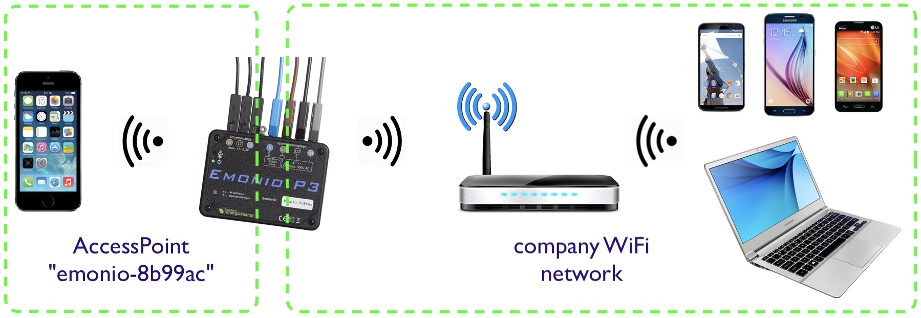
All measuring devices of the type Emonio P3 have the option to use two wireless connections simultaneously. To distinguish these, one is called the Access Point (AP). This network is activated by pressing the button on the side of the device. By default it is active for a period of ten minutes and turned off again when the button is pressed again.
Since this network is not encrypted, its use is only recommended for initial configuration and possibly sporadic retrieval of the measured values or CSV files. A permanent operation of the AP is not recommended. See also chapter Data Protection.
The second wireless connection of the Emonio is used to establish a permanent connection to an existing wireless network. Usually all communication with the instrument should take place over this connection.
¶ Device ID
Each meter of type Emonio P3 is uniquely identified by the device ID. Initially, this corresponds to the pattern "emonio-xxxxxx" where "xxxxxx" is a random hexadecimal string that is unique for each meter.
The factory-set device ID of your meter is printed on the front side (13). Eg: "emonio-a4ce8d".
The name of the device can be changed to a value such as "generator_4" or "cold_storage", as described further below in the chapter configuration. The device_name can be changed at any time and is also reflected in the name of the .csv file and the mDNS name. A reset to factory defaults will restore the original device_id as printed on the front of the Emonio.
¶ Initial Configuration with WiFi
To configure the device or to put into operation the connection of the power supply via the neutral line (9) and phase A (10) is the only thing required. The green LED should turn on and start flashing after a few seconds. This displays either normal operation or, if necessary, the initial configuration.
If the device was reset to factory settings, an initial configuration is necessary. This is indicated by rapid flashing of the green LED. An unconfigured device has no Internet connection configured, so access to the meter is only possible via the access point.
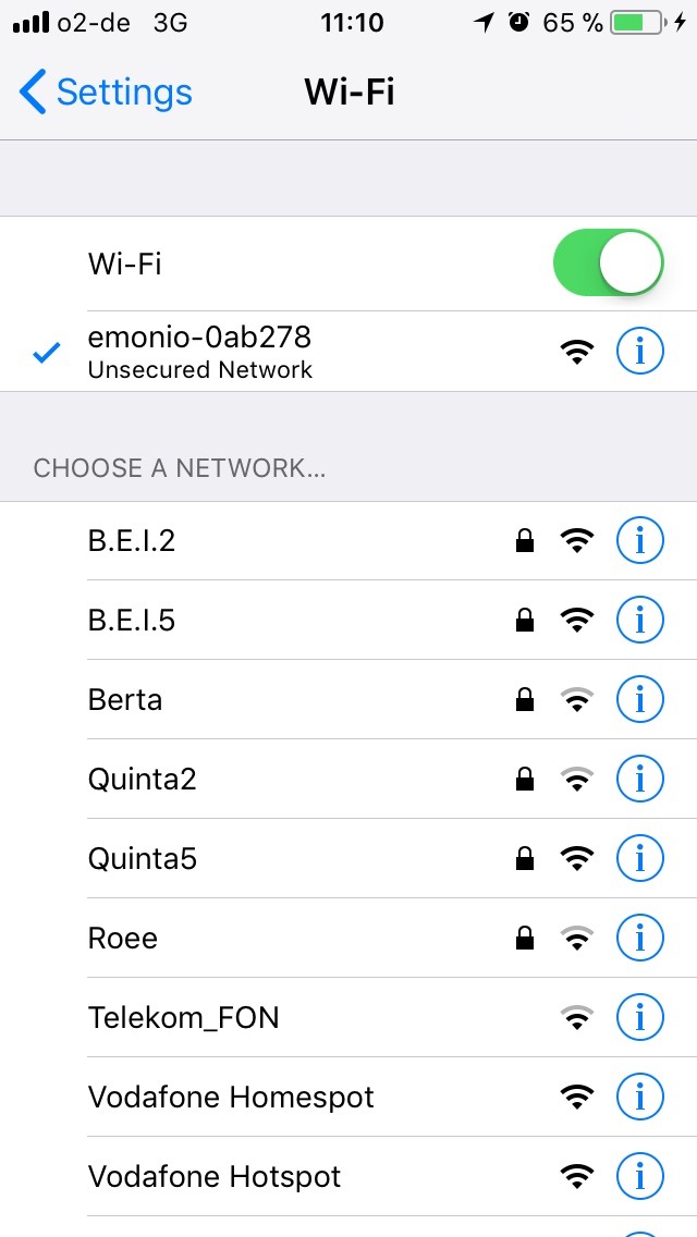
The Access Point (AP) is turned on by pressing the button (1) and its activity is indicated by continuous illumination of the WiFi-LED (3). Once this is done, you can use a computer or mobile phone to connect with this WiFi network. The name of the wireless network corresponding to the device ID (13), which is printed on the front side.
Once the initial configuration has been performed and a user name and password for the admin account were set, all the functions of the instrument are available.
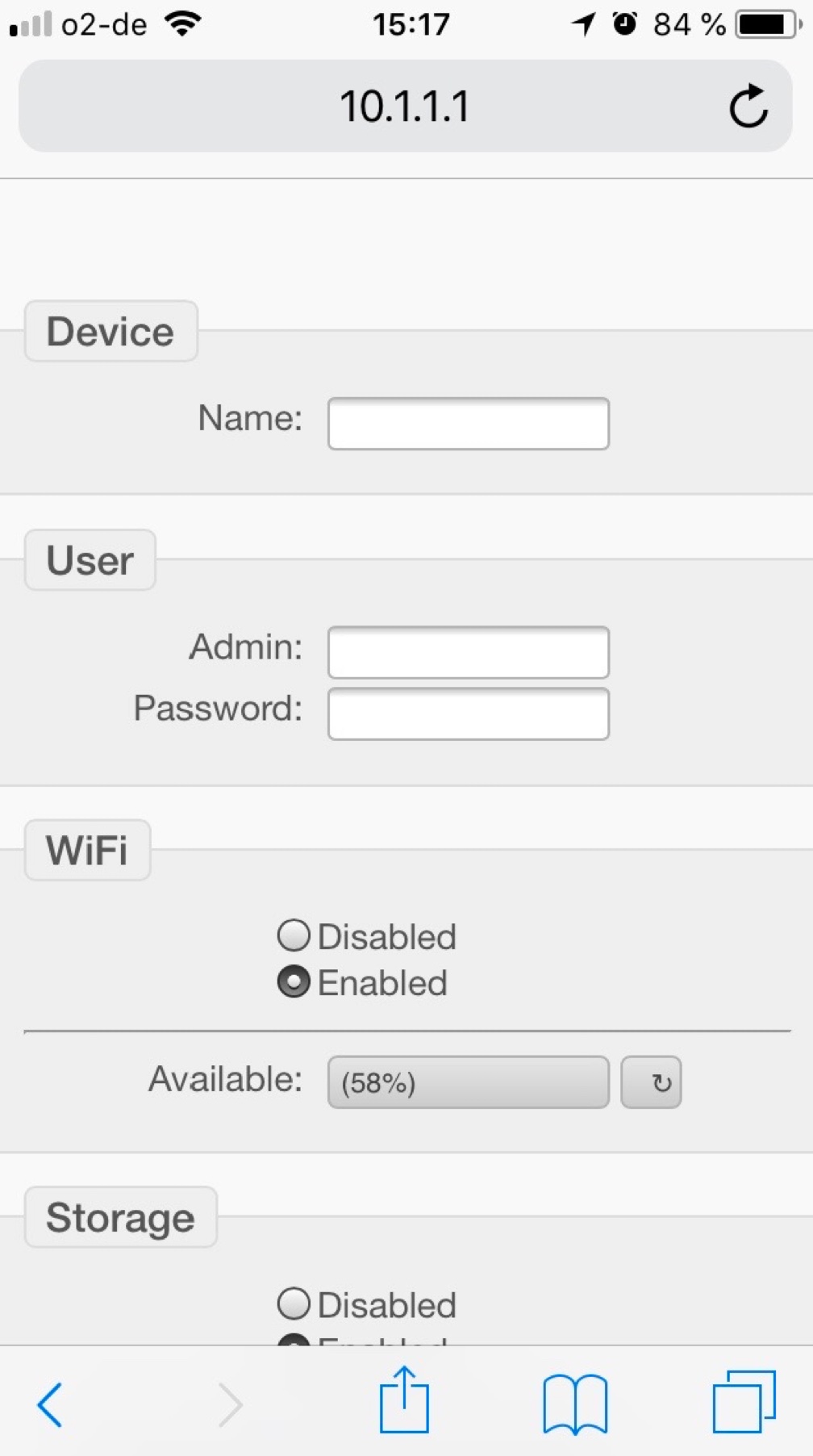
1. Enable access point by briefly pressing the button (1).
 |
 |
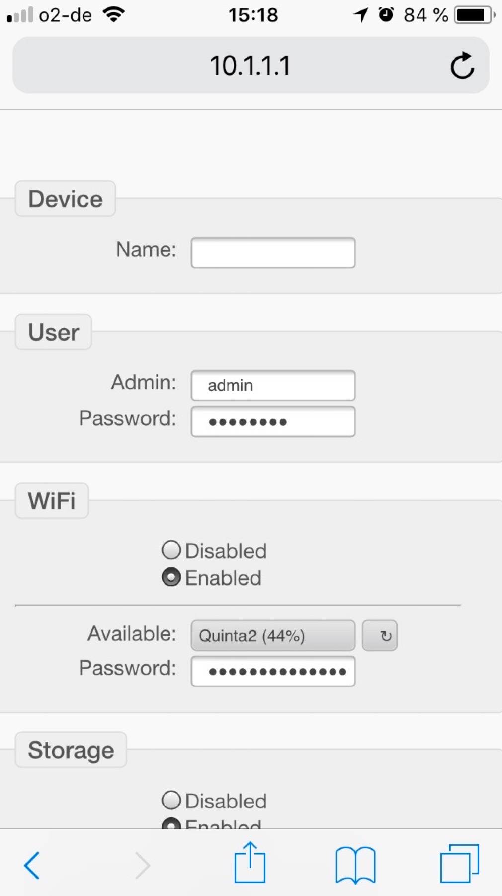 |
| 2. Select WiFi network | 3. Navigate to the site http://10.1.1.1 via web browser. | 4. Admin account and (optional) WiFi is configured. ==> Save & Restart. |
¶ Initial Configuration with App
Emonios of the 2. generation (model 'Efate', since ca. December 2020) have the possibility to communicate using a direct connection in addition to WiFi. To use this option, an App is available for both Android and iOS. Requirement is to use at least Android version 5.1 or iOS version 13.0 or greater.
Download the Emonio App:
 |
 |
| Google Play and the Google Play logo are trademarks of Google LLC. | Apple and the Apple logo are trademarks of Apple Inc., registered in the U.S. and other countries. App Store is a service mark of Apple Inc., registered in the U.S. and other countries. |
You can find an introduction and description of the App in our Wiki at: https://wiki.emonio.de/en/app
¶ Operation
When the initial configuration is done, the Emonio begins to transmit or record measurement data after only about 10 seconds.
There are the following two modes of operation:
- Offline-operation (Recording the measurement data in the internal flash memory): Select this operation mode if no wireless network is available or transfer of data using WiFi is not desired or useful. All data will be stored internally in a CSV-file.
- Online-operation (Transmitting the measurement data to an energy management system, for example: https://pro.emonio.de by means of WiFi network) : The optional smaller intervals of an online measurement allow a closer examination of the energy data and provide customers and energy consultants or technicians with access to live data while the energy monitoring is executed. In additional the recording of CSV files in the internal memory is possible.
¶ Access via AP (internal Access Point)
If no wireless network is available or if the Emonio has not been configured accordingly, access to the instrument can only take place via the integrated access point. Switch it on for a (default) period of ten minutes by pressing the button (1). The activity is indicated by continuous illumination of the WiFi LED (2). Connect directly to the wireless network of the meter. The name of the wireless network corresponds to the device ID (13), which is printed on the front side. You can access the Emonio via a web browser by using the address: http://10.1.1.1
You can deactivate the access point again by pressing the button (1) once more.
¶ Access via WiFi (with configured Internet connection)
If you have already configured an Internet connection for your meter and are using your laptop or mobile device in the same (wireless) network, you can access the device via the mDNS name. This is composed of the device ID and the postfix .local together.
For example: http://emonio-a4ce8d.local or http://motor_4.local or http://solar_input.local
¶ Access via direct connection
Newer models of the Emonio P3 provide the ability to communicate via a direct connection in addition to WiFi. To use this communication method, please use the Emonio App which is available for both iOS and Android. Please see: https://wiki.emonio.de/en/app
Please be aware that the direct connection functionality is turned off while the AccessPoint (AP) is active!
¶ Access via Telnet
You can communicate with your meter using Telnet to enjoy the speed and convenience of the command line. A list of all commands can be found in the chapter command line. However, the Telnet protocol provides no encryption, so it is recommended to only be used via a secure wireless network or an additional VPN.
¶ Admin- and User-Account
The unit offers two different accounts:
- The admin account has read and write permissions.
- The user account only has read permissions.
The 'user' account offers all the options to display data, meter readings and to retrieve the .csv file, but all functionality to change values or settings does not exist. This also applies to the available commands on the command line. This user account should be used to provide an employee access to the data without exposing them to the danger that settings could be inadvertently changed or data to be erased.
To enable this user account, a user name must be entered. The account name and password can be freely selected.
¶ Login
Connected via local WiFi network, point your web browser to: e.g.: http://emonio-0f33fc.local
or
Connected to the access point of the Emonio, use web address: http://10.1.1.1
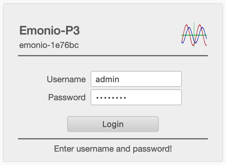 |
You will be asked for a valid login to the Emonio. Here you use the credentials that you specified during the initial startup.
|
¶ Menu
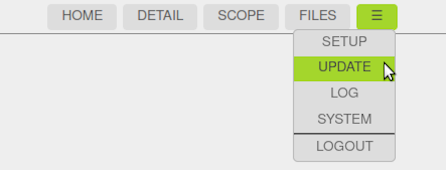 |
After logging in you are on the home page ( "HOME") of the instrument. The various sub-pages are accessed through the menu at the top.
|
¶ Home / Meter Function (“HOME”)
|
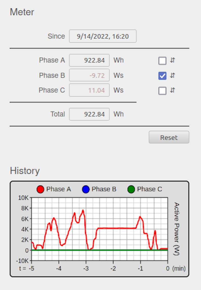
On the home page ( 'Home') of the Emonio you see the energy consumption since the last reset of the counters. The counter values are set to zero by clicking on 'Reset', after an additional security pop-up ("Are you sure ...") is confirmed. It is highly recommended to reset these counters when a new measurement begins. If the supply voltage for a phase is less than 48V, it is displayed with less contrast. Energy data for such 'inactive' phases is not transmitted via Telemetry.
Since of version 3.0.31 a graph showing the last five minutes of energy consumption is also displayed on this page. The left picture shows an Emonio in single-phase operation (measurement of a single consumer with 230V). |
¶ Detailed Measurements (“DETAIL”)
|
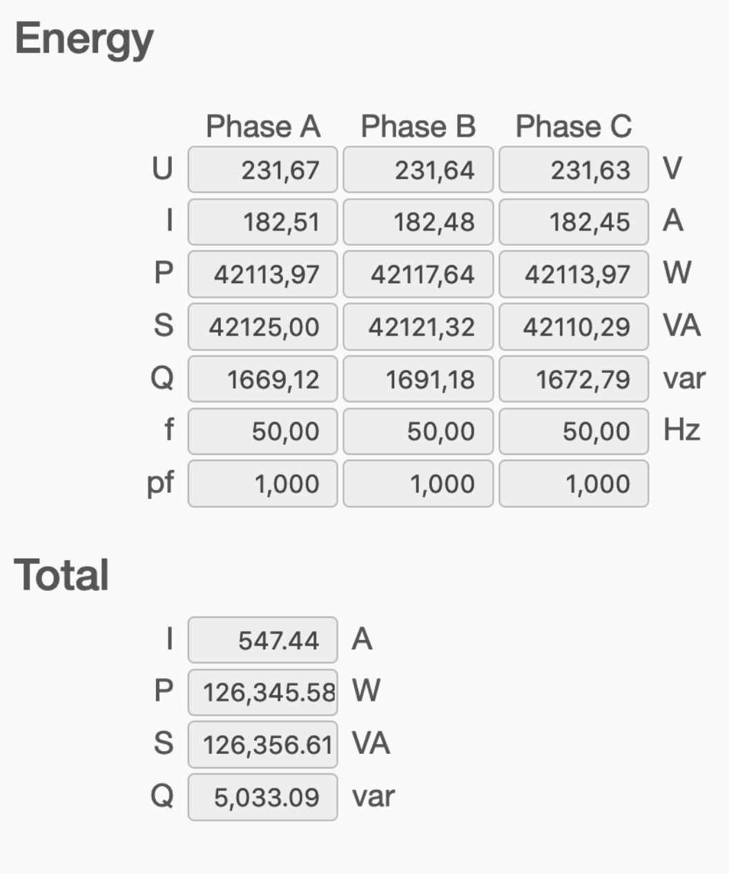
All electrical values can be found on the page "Detail". The following specifics are displayed on this page:
If the line voltage for any phase is less than 48V, these values will be shown with less contrast. No energy values will be transferred via Telemetry for these 'inactive' phases. |
¶ Oscilloscope (“SCOPE”)
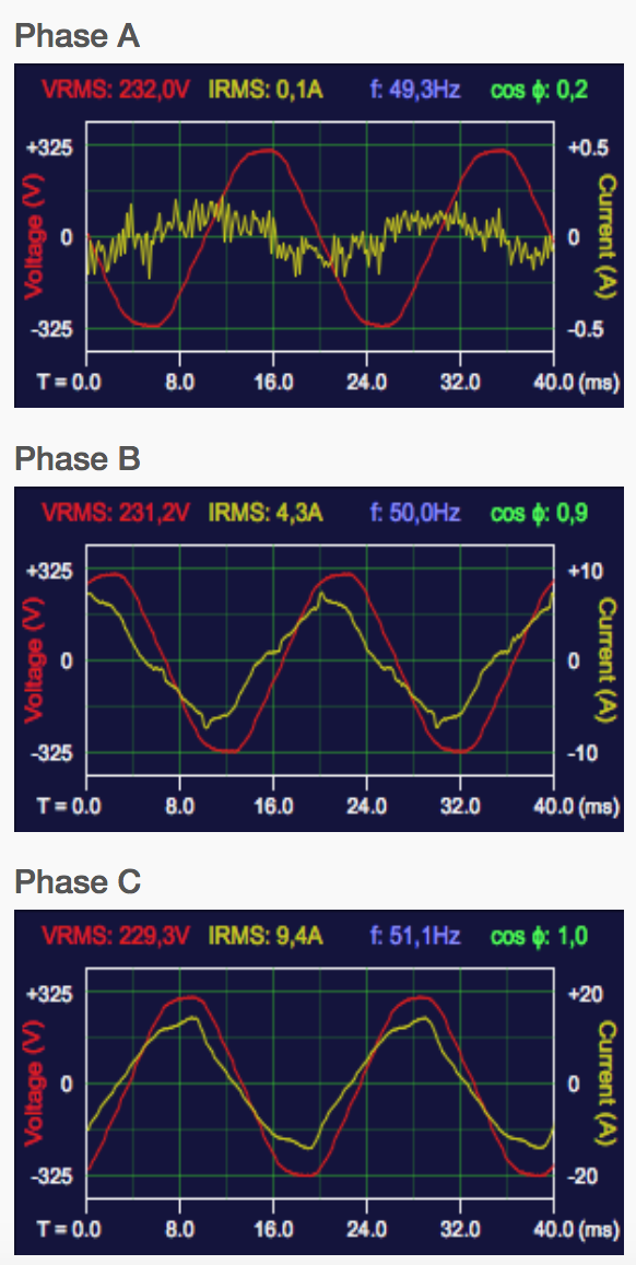 |
The exact graph of current and voltage and the current measured values of voltage, current, frequency and power factor are indicated on the page "SCOPE". This view is also very well suited to verify the phase angles or the proper connection of the voltage samples to a three-phase connection: The voltage curves in a right-handed three-phase electric circuit start for phase A at the zero point, for phase B at the voltage maximum and Phase C at the voltage minimum. The display areas for voltage are: 60, 170, 325, 400 V (peak) For current these are: 0.5, 1, 2, 5, 10, 20, 50, 100, 200, 500, 1000, 2000, 3000A (peak) |
¶ Internal Storage (“FILES”)
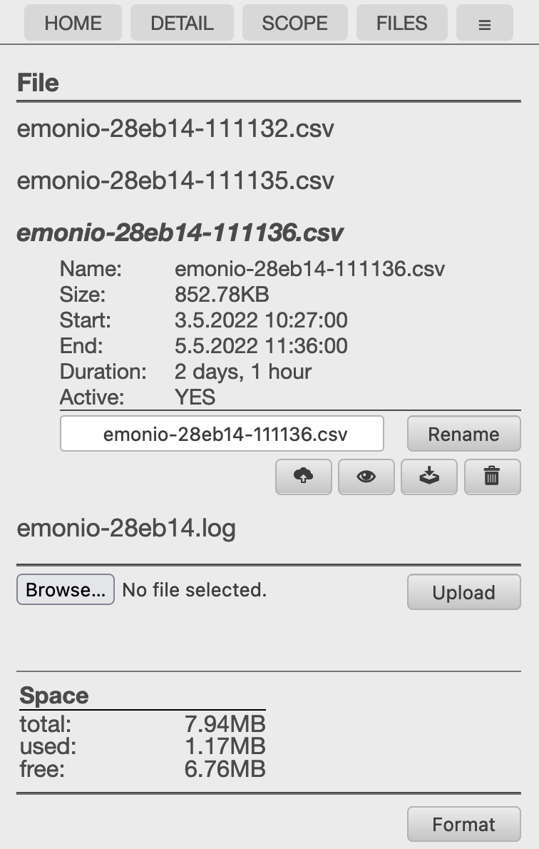 |
If the local storage of measured data is activated, values are stored in an CSV-file. The file is named after the device and can be displayed directly in the web browser, downloaded or deleted. New since version 3.0.37 is the icon for file upload via telemetry. This action is described in more detail in the next section. Furthermore, an optional log file shows the detailed activities of the unit. An optional TLS root certificate to be used with a different telemetry server can be uploaded here. The certificate file must be named “ca.crt” and will be moved to the flash memory upon it's first use. |
¶ Telemetry Upload
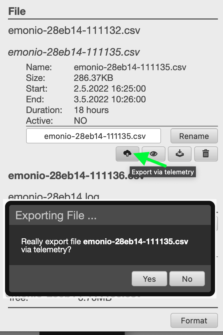 |
Since version 3.0.37 the telemetry upload function has been added: If you click the cloud/arrow symbol on the 'file' page, after confirmation the Emonio will begin to upload the CSV-file using the telemetry protocol to the configured server (e.g. https://pro.emonio.de). During this process, the yellow WiFi LED will flicker to show the data transfer. The file to be transferred will be renamed to ... .exp. As soon as the transfer is finished, the file will be renamed again to ... .exp.ok. Of course you can transfer this file also to your computer. In that case please don't forget to change the file ending from .exp.ok back to .csv so you can open it with a spreadsheet software. Should the transfer be interrupted, it will continue where it left off when the interruption has been resolved. Important prerequisites for this process is a working internet connection using WiFi as well as correctly configured telemetry settings. |
¶ Configuration (“SETUP”)
This will be thoroughly discussed in the chapter configuration.
¶ System Events (“EVENT”)
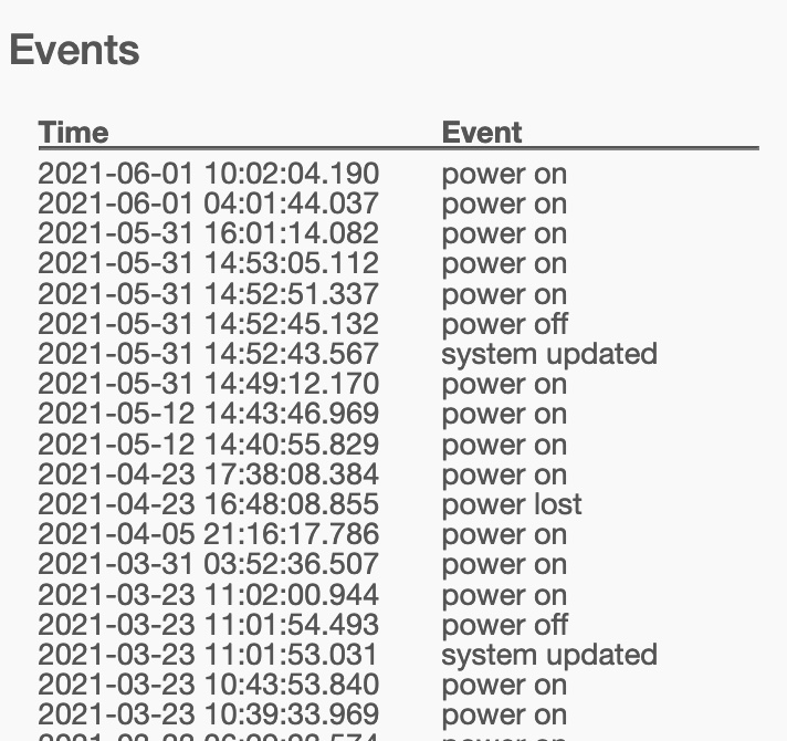 |
Emonio models starting from hardware revision 2.1 ("Efate") will log system events to be shown on this page. Following some of the events that are stored: Start and shutdown of the device Firmware update Voltage disruption Reset to factory defaults ... |
¶ Software Update (“UPDATE”)
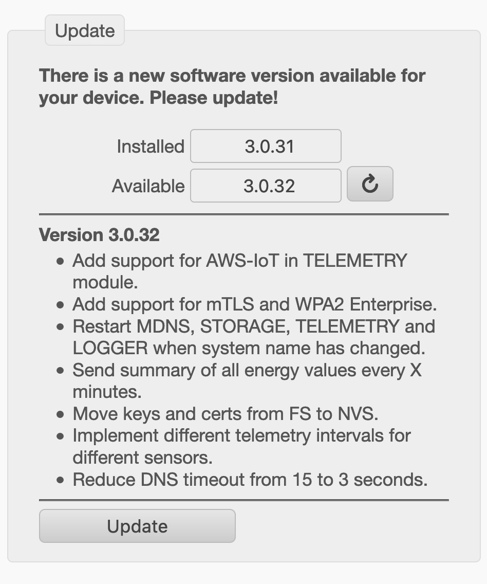 |
Your meter has the possibility to update its own operating system ("firmware") over the Internet. By default, the device will search once a day for an update. Should newer firmware be available, this is indicated here. The update is initiated by clicking on the appropriate button and usually takes about two minutes. It is highly recommended to keep the meter updated to the latest version, as we are constantly adding new features and errors of previous firmware versions are eliminated. |
¶ Diagnosis (Logfile)
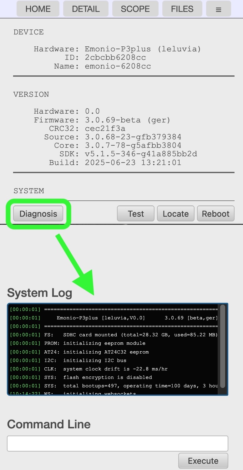 |
If diagnosis / logging is enabled, you will find the “Diagnosis” button at the bottom of the SYSTEM page. The last lines of the log file are displayed on that page. Here you will find detailed information on the inner workings of the Emonio and are able to diagnose potential faults. For example, problems with the network connection, the telemetry server or the like.
Log files in the file system are periodically truncated to prevent the filesystem from filling up. When using the X1 extension and an SDhc card, the log file will be able to grow up to 512kB before being truncated. |
¶ System Information and Reboot (“SYSTEM”)
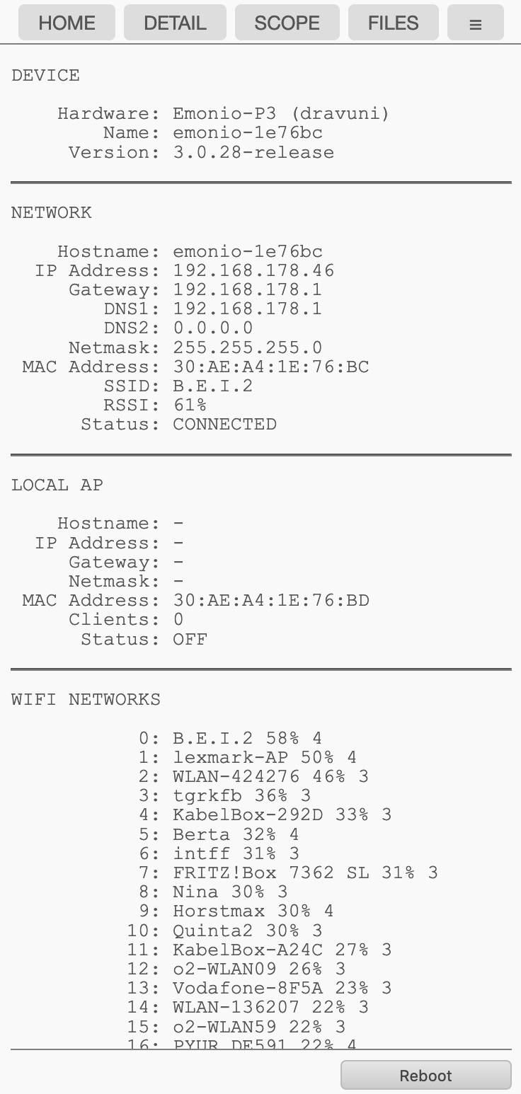 |
On the 'SYSTEM' page you will see information about the hardware and software of the device as well as the configuration of the wireless connection ('Network') and the access point ('Local AP'). The unit can be restarted by clicking on the 'reboot' button at the bottom of the page. To make it easier to locate the device in a crowded installation, the function 'Locate' was introduced. Clicking that button will cause the three LEDs to light up in a pattern for ten seconds.
|
¶ Logout (“LOGOUT”)
 |
To end the session, or to register with another user, click the menu item 'LOGOUT'. After ten minutes of inactivity, the session is terminated automatically. The adjacent menu to the left shows the limited functionality of the user account. |
¶ Configuration ("SETUP")
To perform successful measurements it is useful and in parts necessary to make certain settings on the device. The following section describes all settings of the 'SETUP' page in detail.
All these settings can also be changed on the command line, you will find an overview of the necessary commands for this purpose in the chapter Command Line.
¶ Device Name (“Device”)
 |
By default, this field is blank and the meter uses the factory-set name 'emonio-xxxxxx'. The value of this field will affect the mDNS name of the device and the name of the .csv and .log file. Furthermore, this name can also be part of the values transmitted over the Internet and for example be used in your energy management software. In the attached example shown, the name was changed to UV_2a. This meter is now to be found on the network using the name 'uv_2a' or via the URL http://uv_2a.local. It is recommended to refrain from using whitespaces or special characters for the device name as this might complicate finding the device via mDNS and/or entering the name in the webbrowser. |
¶ Admin Account (“User”)
 |
Here username and password can be set for the 'Admin' account. In the extended configuration a non-privileged 'user' account can also be configured. |
¶ WiFi Configuration (“WiFi”)
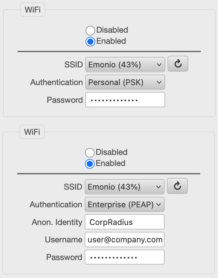 |
If measurement data is to be transmitted by means of WiFi, an existing connection can be configured here. To do this, select the desired network (SSID) from the list and enter the appropriate password. The percentage next to the SSID indicates the strength of the WiFi signal. Use the button on the side to refresh the network list. A non-existent or hidden network can be configured by selecting the three points ("...") at the bottom of the list and then enter the appropriate SSID in the new field. Certificates for using WPA-Enterprise (TLS) can be uploaded via the “FILES” page. The names of these files must be assigned as follows:
|
¶ Local Recording of Measurement Values (“Storage”)
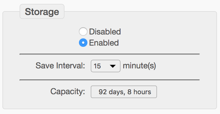 |
The recording of the measured values in the local flash memory is enabled by default. The quarter-hour average values of U, I, P are written for each of the three phases in a single CSV file. Each line will start with a Unix timestamp and the date and time in human readable format. An approximate estimation of the maximum recording time will be shown in the field 'Capacity'. |
¶ Description of CSV-File Contents
All electrical values found in the CSV file are root mean square values, averaged over the measurement period. If for example the storage interval is set to one minute, the result is an arithmetic average of the 26.000 samples per second x 60 seconds.
The extreme values (min and max) are different: These are the smallest and largest 0.1 second measured values in the selected recording interval. When examining very small periods of time, it makes sense to only look at the power values, since the RMS values need time to 'level out'.
Following you find all columns that can be configured. Depending on the selected values to be stored, not all columns have to be present. There can be additional columns at the end with environment values of optional sensors (temperature, humidity, CO2, counter, ...).
- timestamp: Unix-timestamp (seconds since 1.1.1970). This field is used to exchange time information between IT systems.
- localtime: Date/time in user configurable format.
- vrms: Voltage in Volt, arithmetic mean of the three phases.
- irms: Current in Ampere, sum of all three phases.
- watt: Active power in Watt, sum of all three phases. If the phase angle between voltage and current of one phase is > 90°, the sign will be negative.
- var: Reactive power in var, sum of all three phases.
- va: Apparent power in VA, sum of all three phases.
- freq: Frequency in Hertz, arithmetic mean of the three phases.
- kwh: Elektrical work in kWh, since resetting the counters, sum of all three phases.
- pf: Power factor, arithmetic mean of the three phases.
- kwh_in: Electrical work in kWh, since resetting the counters. Sum of all energy, consumed.
- kwn_out: Electrical work in kWh, since resetting the counters. Sum of all energy, delivered.
- connected_a: Indicator for activity of this phase (A). ‘1’ = Phase A was active (meaning > 48V) during the whole measurement interval. ‘ 0' = Phase was inactive (meaning < 48V) during the whole measurement interval.
- vrms_a: Voltage in Volt, Phase A.
- ...
- vrms_min_a: Minimum voltage during the measurement interval.
- vrms_max_a: Maximum voltage during the measurement interval.
- irms_min_a: Minimum current during the measurement interval.
- irms_max_a: Maximum current during the measurement interval.
- watt_min_a: Minimum power during the measurement interval.
- watt_max_a: Maximum power during the measurement interval.
¶ Transmitting of Measurement Values (“Telemetry”)
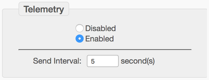 |
By default each Emonio is equipped with valid settings for the secure transmission of measured values to the analysis portal of the Emonio GmbH on https://pro.emonio.de. Authentication is performed via token. |
¶ Current Sensors (“Current Sensor”)
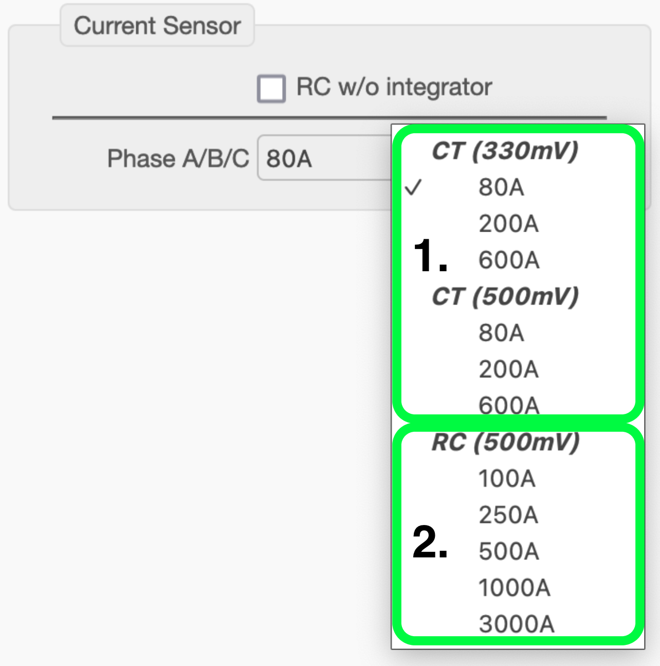 |
It is indispensable to correctly configure the connected current sensors! There are three different types of current sensors available: 1. CTs (Current Transformers)
2. RCs (Rogowski Coils) with integrator
|
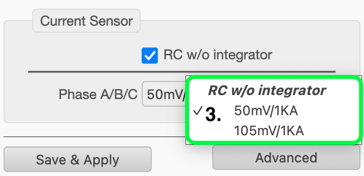 |
3. RCs (Rogowski Coils) without integrator
These sensors do not come with an integrator in the cable. The only marking is the one on the lock of the coil itself. There are currently only two versions: 50mV/kA and 105mV/kA. Those coils can be used up to a maximum current of 1.2kA and 4.7kA accordingly. |
¶ Saving the Settings (“Save & Apply/Reboot”)
 |
To activate the new settings, click the 'Save & Apply' or 'Save & Restart' button at the bottom of the setup page. The device will save the settings and (if needed) do a reboot. |
¶ Advanced Configuration (“Advanced Setup”)
Settings not frequently used can be found in the expanded configuration. This can be accessed via the button 'Advanced' at the bottom of the Setup page. We will show some of the advanced settings in detail.
¶ Unprivileged User
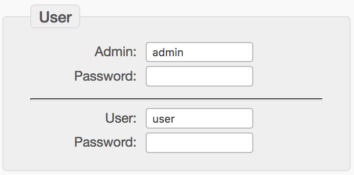 |
If you need an additional account to access the Emonio with limited user rights, it can be defined here. The 'User' can only read but not change any settings or delete data. |
¶ WiFi / AccessPoint (AP)
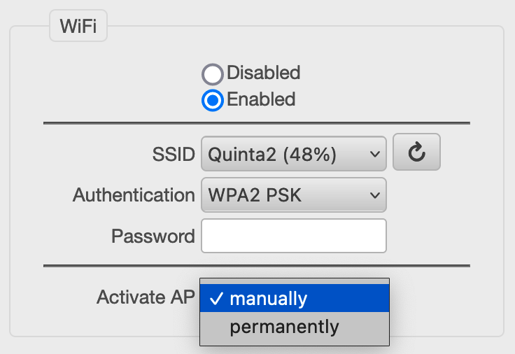 |
The Access Point (AP) usually is manually activated/deactivated and will turn off by itself after 10 minutes of not using it. Here you can permanently enable it. Beware that if the AccessPoint (AP) is active, the direct connection functionality needed to communicate with the Emonio App is not available ! |
¶ Network Settings (IP)
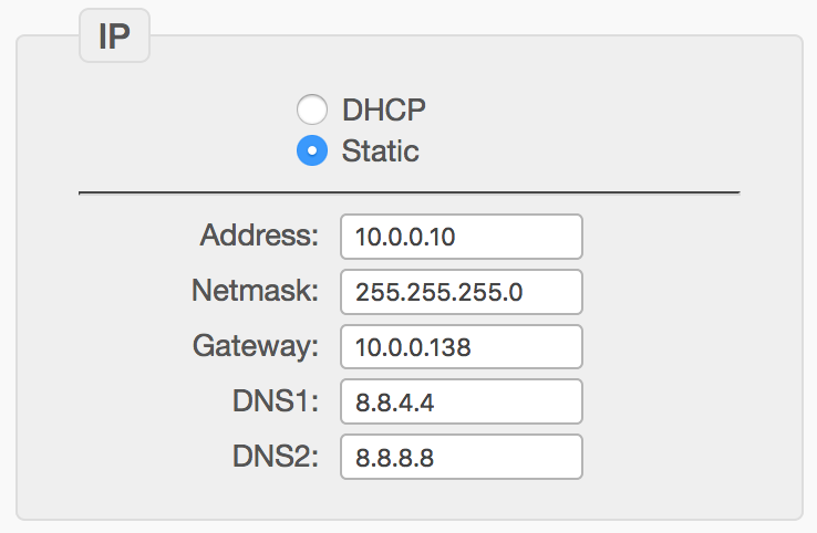 |
If it is necessary to manually configure the TCP/IP settings for the wireless connection, the automatic DHCP configuration can be deactivated here to enter all values manually. |
¶ Transmitting the Measurement Values ("Telemetry")
To send the measurement data as well as monitor the status of the Emonio, there are several communication protocols based on MQTT and HTTP that can be used. The data is transmitted in JSON or XML format and encrypted using TLS.
By default the Emonio is equipped with the root certificate of LetsEncrypt.org. If an alternative certificate is required, this can be stored in the flash memory via file upload.
¶ Thingsboard
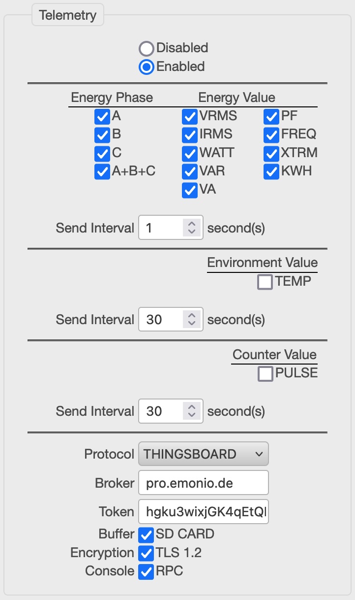 |
In the advanced view you can control in detail the parameters that are sent over the network. The different sensors (energy, environment and counter) can be configured to have different transmission intervals.
Each Emonio is factory-equipped with valid settings for the secure transmission of the measured values to the analysis portal of the Emonio GmbH at https://pro.emonio.de. The authentication is done using a preconfigured token.
Encryption of the data during transport (TLS) is enabled by default. The Emonio can be remote controlled using RPC. In order to use this functionality, 'Console/RPC' must be activated. A more detailed description of the RPC options can be found in section command line.
|
¶ MQTT/Generic
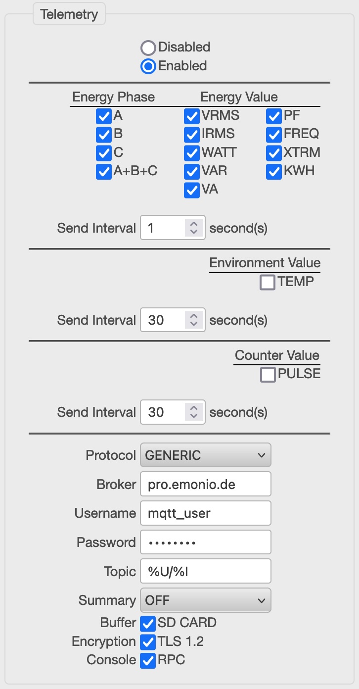 |
If you want to use your own MQTT broker (e.g.: Mosquitto) you'll find all necessary settings in the protocol 'Generic'. Besides the standard settings of server (broker), user, password, there are several place markers that can be used for topic:
|
¶ EmonCMS
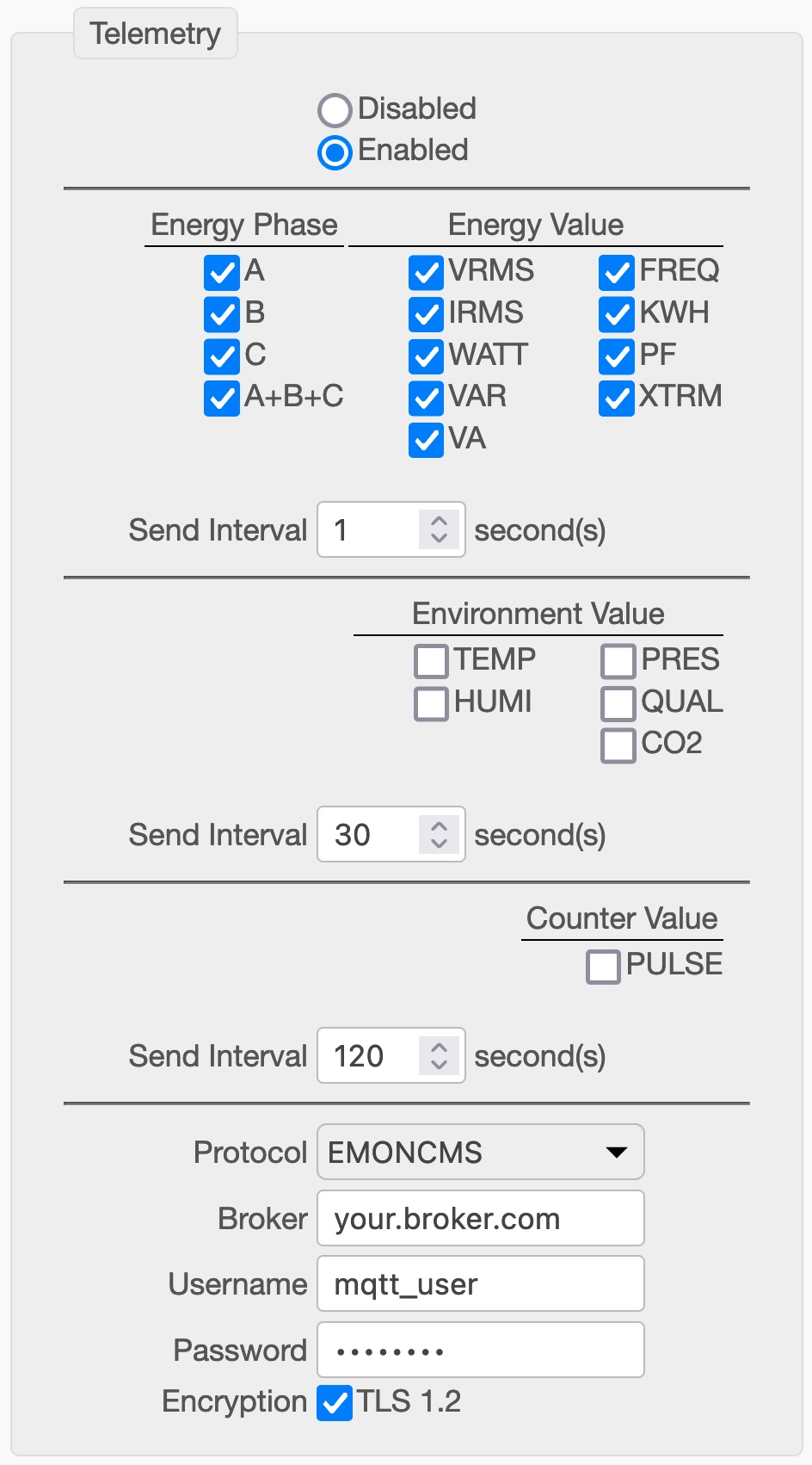 |
You can register for an account on https://emoncms.org or download the software to your own server. To use this protocol you need the correct URL that is: http://emoncms.org/input/post The authentication is based on a token that has to be generated on the server and saved in the 'key' field. |
¶ AWS IoT
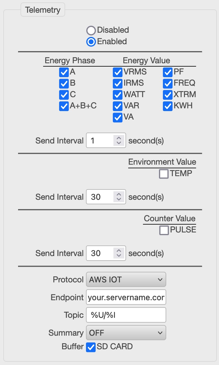 |
Since version 3.0.34 the Emonio P3 officially supports the AWS IoT stack. For a working connection it is mandatory to download and create the correct certificates and store them on the Emonio with the correct names:
These files will be moved to a reserved part of the Flash memory and will be removed from the filesystem when the telemetry module is initialized the first time. If you need to replace or erase these certificates, upload new (or empty) ones with the names above. You have also the possibility to send 'summary' values every x minutes, to be stored separately from the more frequently sent telemetry data.
|
¶ Modbus(-TCP) Server
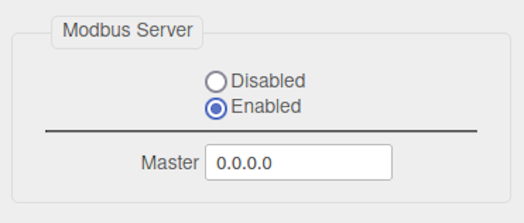 |
Since Version 3.0.29 the Emonio also supports the widely used protocol Modbus/TCP. The Emonio acts as a Modbus slave. In the configuration, the IP address of the Modbus master can be specified, which can query the values of the Emonio. An IP address of 0.0.0.0 allows access by any master. Any other setting restricts access to the specified IP address. For a detailed list of the Modbus registers, please see chapter ModBus/TCP. |
¶ Local Recording of Measurement Values (Storage)
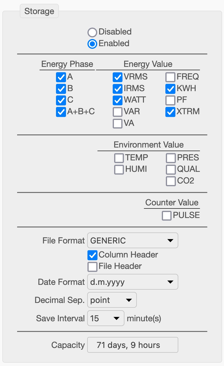 |
Here you can configure in detail which values should be saved in your CSV file. To save space, the separate recording of the three phases can be deactivated and the sum/average of all three selected instead (A+B+C). You can choose between the standard CSV-format with separate columns for each value and the 'ITC'-format. The latter will write one value per row and use OBIS-codes to describe the measurements taken. The Environment- and Counter Values are reserved for optional sensors that will be available as add-ons in the future. 'Column header' will add a header line to the file which designates the values. The 'File Header' will add three additional lines to the top of the file showing the Device-ID, Device-name and CSV-Version. These can be used to ease later, automated processing of the file. To ease further processing of the CSV file, the format of the date as well as the decimal separator can be set here. The save (write) interval can be chosen between 0.1 second and one hour. Capacity will show an estimation of the recording time with the currently configured settings. |
¶ Automatic File Transfer (Upload)
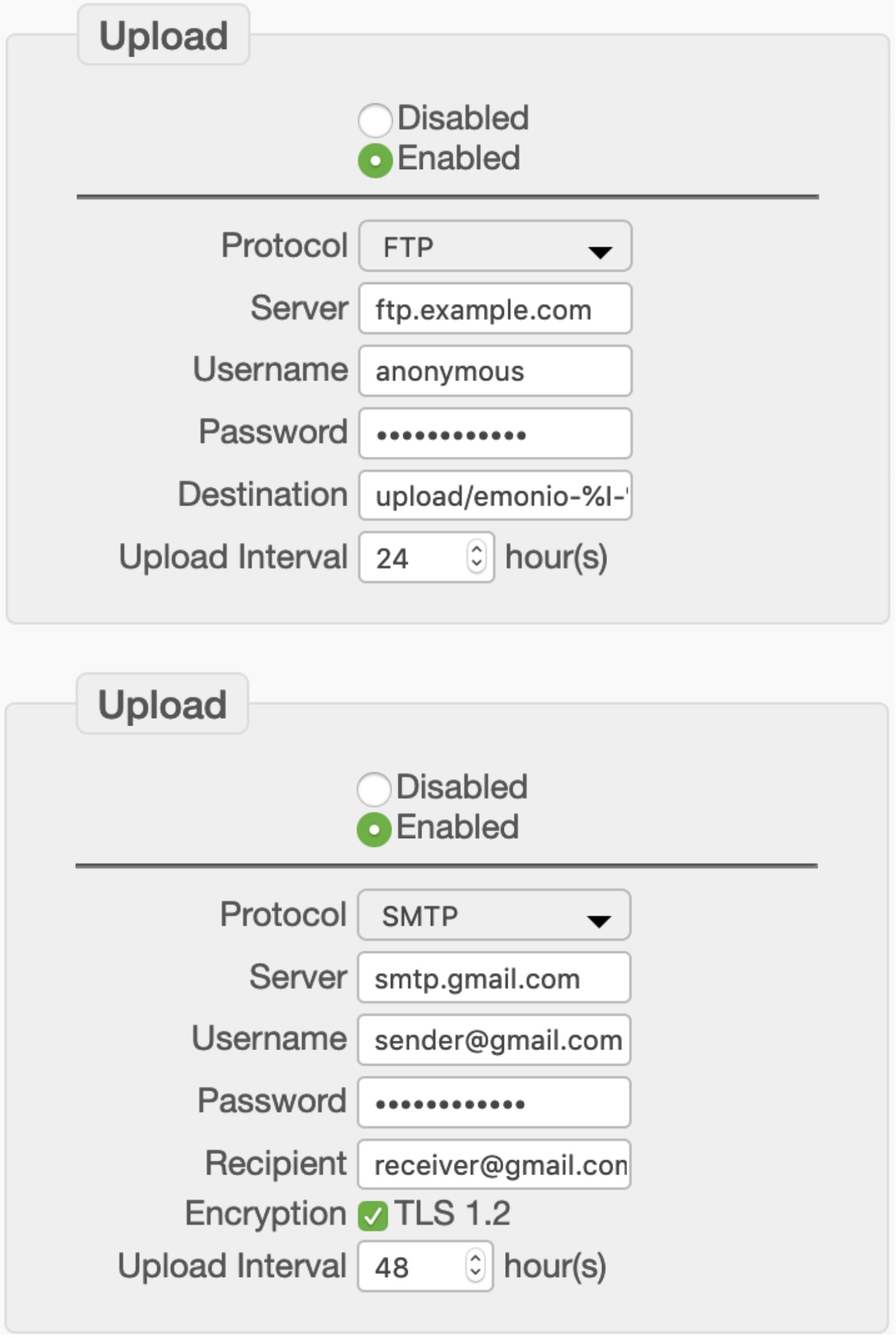 |
Locally stored CSV-files can be periodically uploaded to a remote location. To do so you can use FTP, SMTP (i.e. E-Mail) or HTTP upload protocols. When configured correctly, the files will be uploaded and upon success are deleted from the device. The following place markers can be used for the destination:
To use SMTP upload you need access to an email account like Gmail or the like. The files will be sent as a MIME-encoded attachment. For encrypted SMTP only TLS can be used. STARTTLS (like it's being used on outlook.com) is not supported at the moment. By default SMTP will try to use port 465. Specific port numbers may be used by adding :port to the server name.
|
¶ Current Sensors
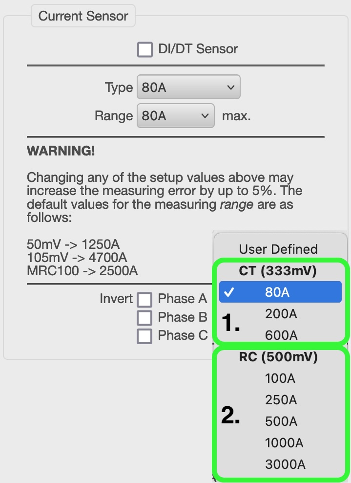 |
All devices are correctly configured when they're first sent out to the customer.
After a factory reset it is essential to configure the current sensors correctly !
In general there are three different types of sensors: 1. CTs (Current Transformers): These are transformers with an iron core. Since 2020, we only sell the type “80A/333mV”. 2. RCs (Rogowski Coils) with integrator: These current sensors are flexible and have a fixed maximum current that is printed on the rectangle integrator in the cable, usually about 20cm from the connector. (e.g.: 100A or 500A). We stopped selling this type of sensor in 2021.
|
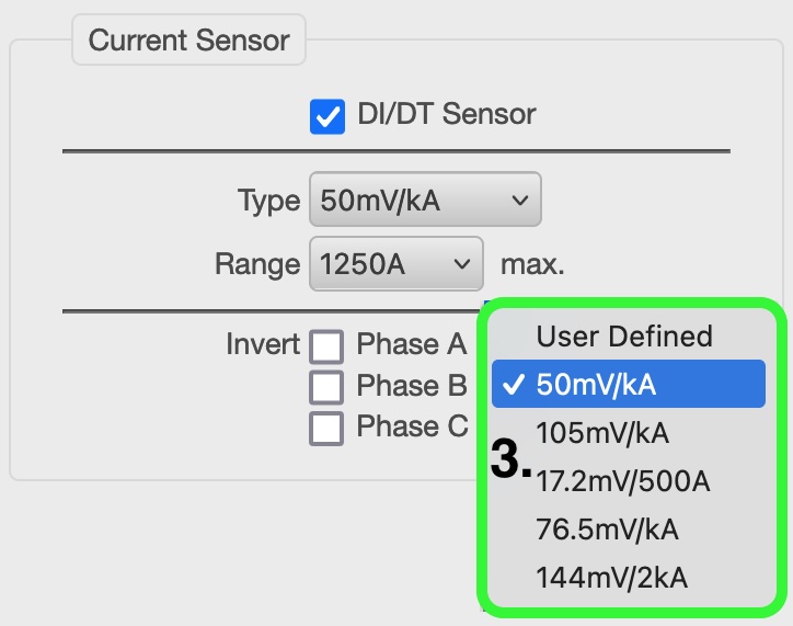 |
3. RCs (Rogowski Coils) without integrator: These current sensors usually have a ratio printed directly on the closing mechanism. (e.g. 50mV/kA, 105mV/kA or 333mV/kA). These are the standard current sensors shipping with the Emonio since 2021 !
In addition you have the option to 'virtually reverse' the sensor. In case a sensor was mounted the wrong way around you can turn it here and do not have to physically reinstall it. |
¶ Pulse Counter (Counter)
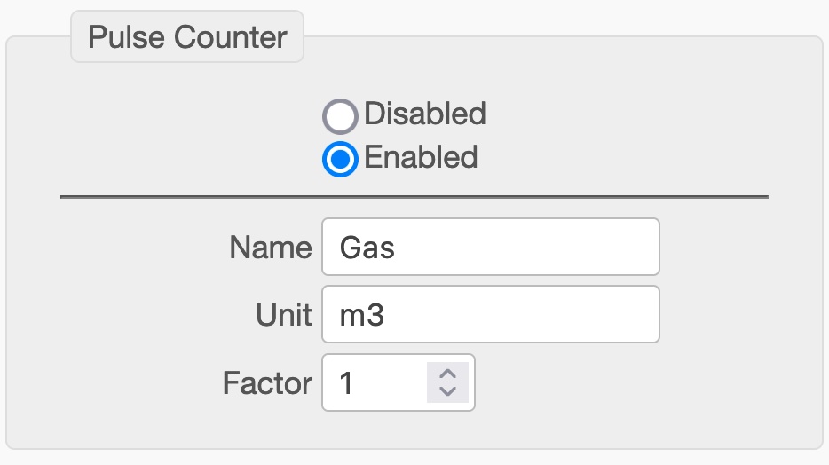 |
If the Emonio is equipped with the optional 'X1' extension, an additional pulse counter may be configured. Specify a factor, name and unit for the pulse counter and these values will be transmitted with the other telemetry values. If activated, the pulse counter will also be shown on the 'HOME' page of the Emonio. |
¶ Temperature Sensors
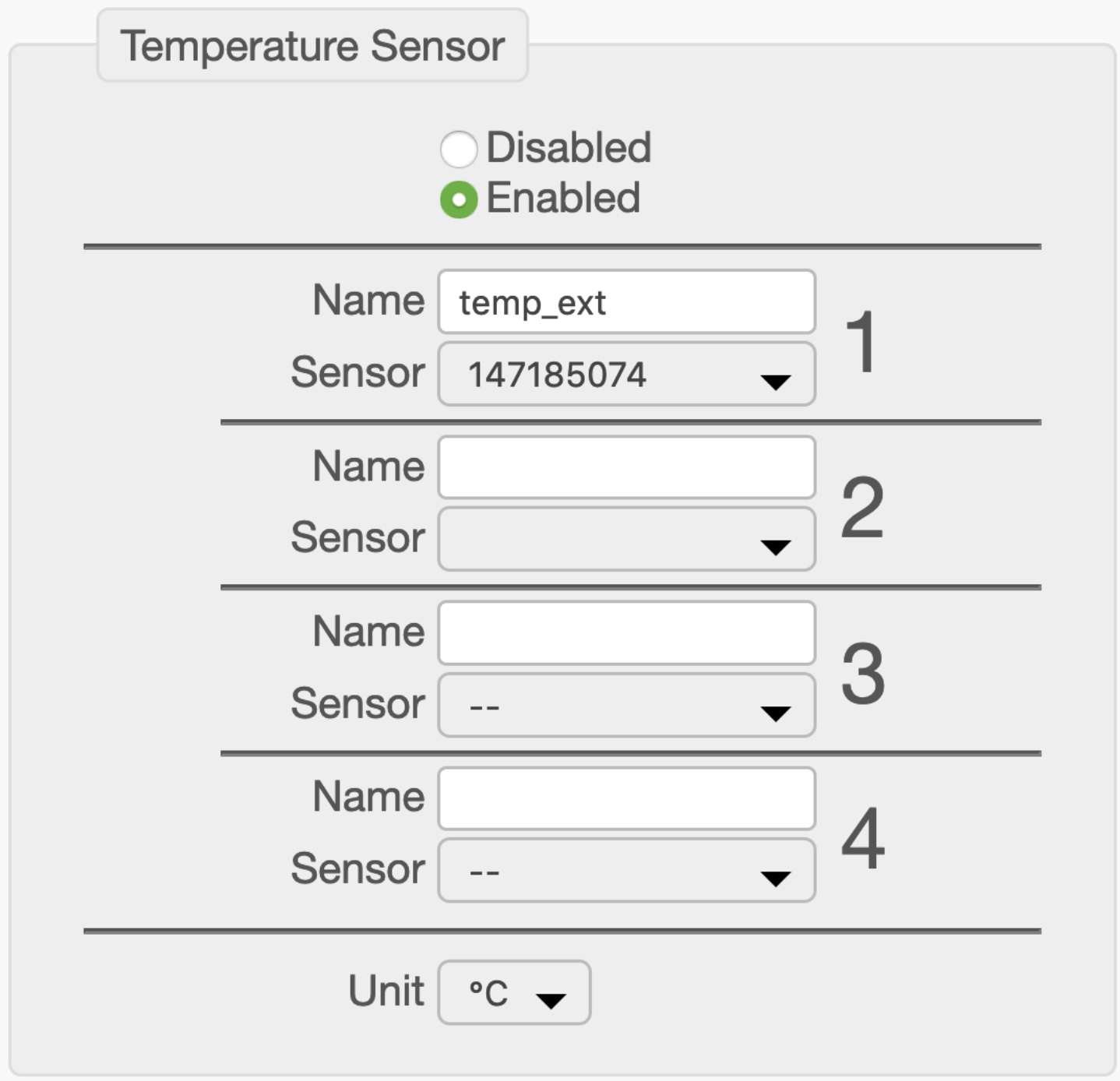 |
Only recently there is the option of adding an additional port to the Emonio P3 to connect up to four DS18x temperature sensors. These sensors are identified by their sensor ID and can be given a name using this configuration dialog. The additional columns in the CSV file and the additional fields in the MQTT data are named according to the designators you add here. Additionally there is the possibility to select the unit from ‘°C’ for Celsius, ‘K’ for Kelvin or ‘F’ for Fahrenheit. |
¶ Timezone
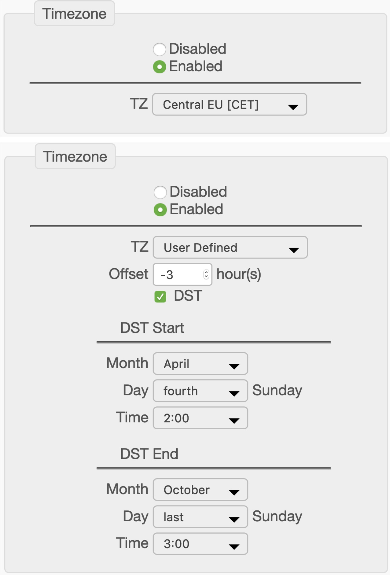 |
The local timezone is important for a correct recording of the time (in the CSV files) and (if applicable) the switching to/from daylight saving time (DST). Some of the more important or common timezones are preconfigured and can be selected directly from the menu.
If your timezone is not in the menu, please select 'User Defined' and configure all relevant parameters as follows: Most important is the offset from UTC (previously also known as GMT). If your timezone needs the swithing to/from daylight saving time, the exact date and time for these changes can be configured here. |
¶ Clock
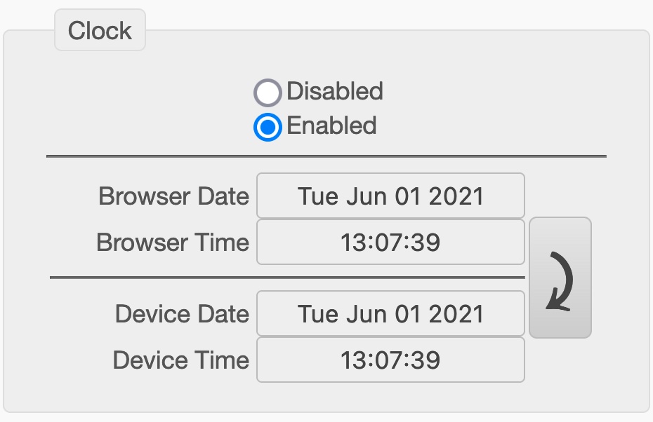 |
The section 'Clock' allows you to synchronise the built-in battery-backed real time clock with the time on your computer. Click on the arrow to the right and the time of the Emonio will match up with your web browser. An exact time is important for the proper recording of CSV files! If the Emonio is connected to the Internet, the internal clock is synchronised automatically with an Internet time server every 24 hours. |
¶ Firmware Update (Update)
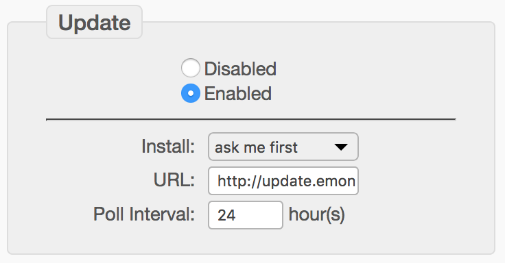 |
By default the Emonio will look for updated firmware once a day. If new software is found, the user will be redirected to the update page once after login. This is either installed automatically or after confirmation via the Update page. It is strongly recommended to always keep the device up to date, as new functions are constantly being added or bugs fixed. |
¶ Telnet
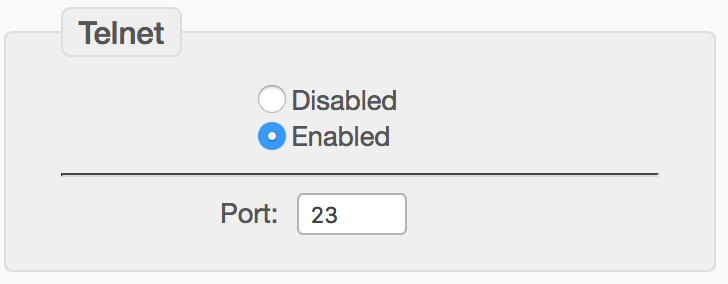 |
Access via Telnet can be enabled here. The default port 23 can be changed. For a detailed description of the command line, please see chapter command line. |
¶ Diagnosis/Logging
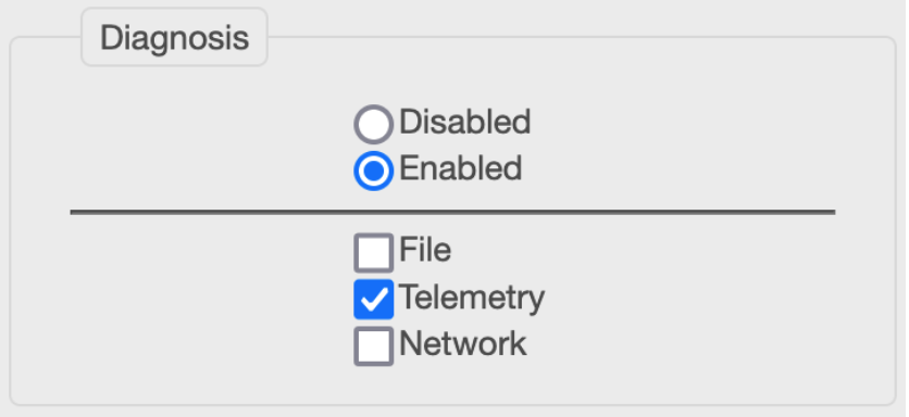 |
Diagnosis/logging can be activated for easier troubleshooting. By default, the log is stored locally on the device as a file. The log can also be sent to a log server via MQTT or UDP and port 49152. |
¶ Telemetry Data on the Internet
If the Emonio is configured with a working Internet connection, it will send the measurement data every second to the energy portal at: https://pro.emonio.de. Here all telemetry data is recorded in a database and can be processed and visualised using different techniques.
To obtain a license for https://pro.emonio.de, please visit our webshop at: https://shop.emonio.de
¶ Simple Dashboard
A very simple dashboard showing the consumption of a single three-phase load.
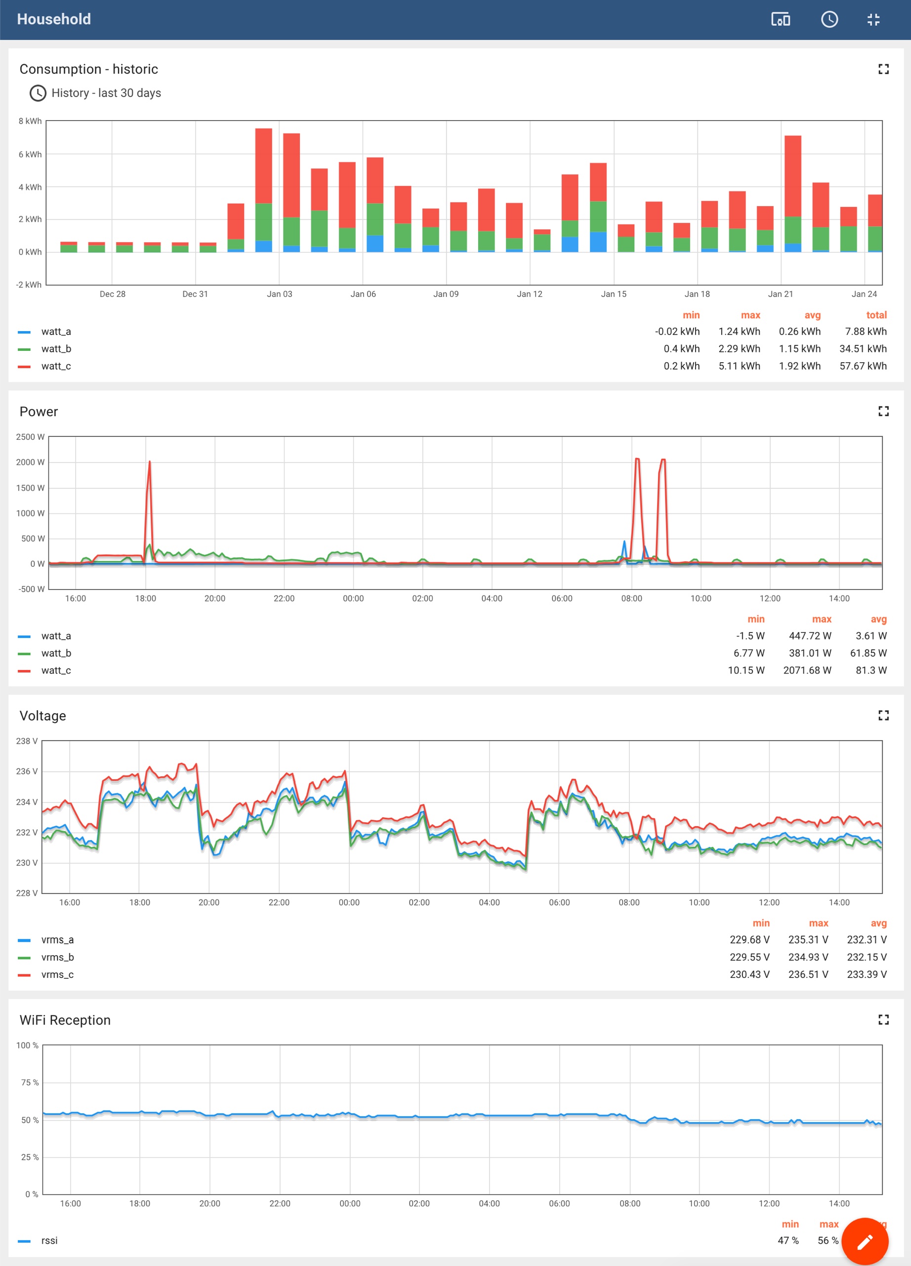 |
Energy consumption by day during the last month
power used
grid voltage
WiFi signal |
¶ Showing several Devices as List
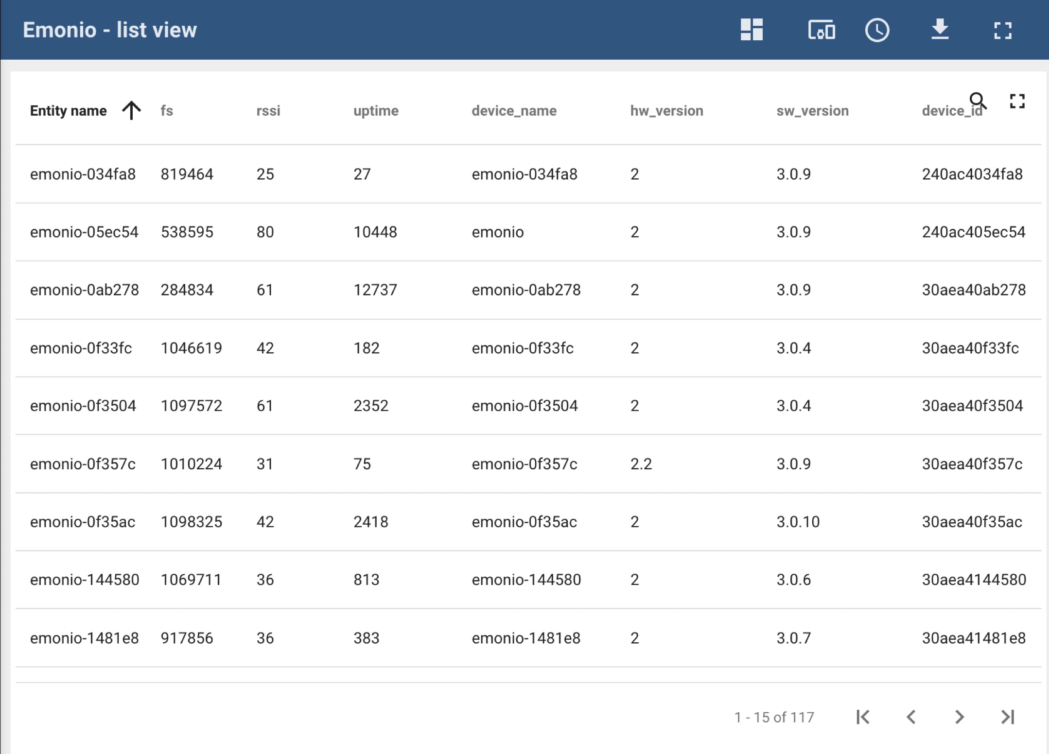 |
The dashboard ‘List View' shows values of several devices in a table. You will get to the detailed view by clicking on a row. |
¶ RPC remote Shell
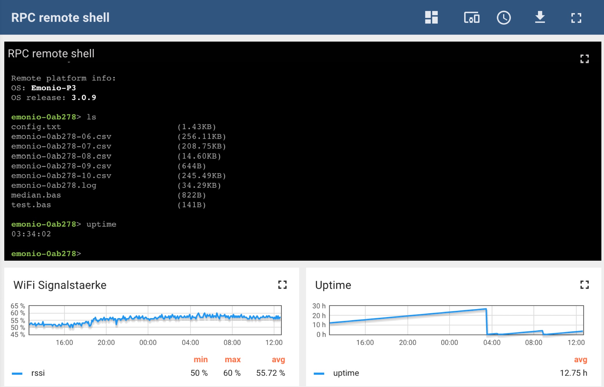 |
The RPC console can be used to send single commands to a remotely installed Emonio or to read/change configuration values. You can find a list of available commands and their limitations in chapter command line. |
¶ Security and Data Protection
¶ WiFi Encryption
Please ensure that the data is always sent using encrypted channels. For WiFi we recommend using WPA2 encryption.
¶ Internal Access Point (AP)
The internal Access Point (AP) of the Emonio P3 does not provide any encryption and should only be used for initial configuration or to quickly access values or download data. The AP is not intended to be used continuously and it is not recommended to enable it permanently*.
If the AP is active, the WiFi-LED (3) will be lit constantly. You can use any WiFi enabled device to connect to the AP's WiFi network and access the Emonios website on http://10.1.1.1. At the same time, the direct connection functionality will be disabled for as long as the AP is active.
* An enabled AP will show up as an open WiFi network on all devices that search for it. It might happen that random devices will connect to the AP (because they think there's free WiFi for them). As the AP does NOT provide an Internet connection, these devices will be offline and not receive any notifications, messages or emails. As this scenario is confusing and inconvenient, the AP should stay in its default configuration 'manual' - which will turn it off after 10 minutes of idle time.
¶ MQTT Protocol
The protocol used for sending telemetry data is MQTT in version 3.1.1.
Transmission of MQTT messages is done using TCP on port 1883 or 8883 (with TLS).
All data is JSON formatted and will be sent every second (by default). Here an example of a MQTT message:
v1/devices/me/telemetry
{
  "ts" : 1752758243316,
  "values" : {
    "egy_vrms" : 234.61,
    "egy_irms" : 2.56,
    "egy_watt" : 331.03,
    "egy_var" : -166.26,
    "egy_va" : 590.58,
    "egy_pf" : 0.561,
    "egy_freq" : 49.97,
    "egy_kwh" : 944.8448,
    "egy_kwh_in" : 950.8435,
    "egy_kwh_out" : 5.9987,
    "egy_irms_n" : 1.79,
    "egy_isum" : 0.0,
    "egy_vrms_a" : 235.11,
    "egy_irms_a" : 0.7,
    "egy_watt_a" : 63.31,
    "egy_var_a" : -48.81,
    "egy_va_a" : 161.16,
    "egy_pf_a" : 0.419,
    "egy_freq_a" : 49.97,
    "egy_vrms_min_a" : 235.09,
    "egy_vrms_max_a" : 235.12,
    "egy_irms_min_a" : 0.59,
    "egy_irms_max_a" : 0.9,
    "egy_watt_min_a" : 61.61,
    "egy_watt_max_a" : 65.14,
    "egy_kwh_a" : 151.351,
    "egy_kwh_in_a" : 154.3108,
    "egy_kwh_out_a" : 2.9598,
    "egy_vrms_b" : 235.49,
    "egy_irms_b" : 1.62,
    "egy_watt_b" : 242.84,
    "egy_var_b" : -115.74,
    "egy_va_b" : 373.96,
    "egy_pf_b" : 0.708,
    "egy_freq_b" : 49.97,
    "egy_vrms_min_b" : 235.44,
    "egy_vrms_max_b" : 235.51,
    "egy_irms_min_b" : 1.44,
    "egy_irms_max_b" : 1.95,
    "egy_watt_min_b" : 241.39,
    "egy_watt_max_b" : 244.94,
    "egy_kwh_b" : 769.4487,
    "egy_kwh_in_b" : 769.4489,
    "egy_kwh_out_b" : 1.0E-4,
    "egy_vrms_c" : 233.21,
    "egy_irms_c" : 0.24,
    "egy_watt_c" : 24.89,
    "egy_var_c" : -1.7,
    "egy_va_c" : 55.46,
    "egy_pf_c" : 0.198,
    "egy_freq_c" : 49.97,
    "egy_vrms_min_c" : 233.16,
    "egy_vrms_max_c" : 233.23,
    "egy_irms_min_c" : 0.21,
    "egy_irms_max_c" : 0.25,
    "egy_watt_min_c" : 23.89,
    "egy_watt_max_c" : 26.03,
    "egy_kwh_c" : 24.0451,
    "egy_kwh_in_c" : 27.0838,
    "egy_kwh_out_c" : 3.0387,
    "protocol" : 3
  }
}
Additionally max. every 60 seconds the following debug data is transmitted:
v1/devices/me/telemetry
{
  "uptime" : 242,
  "stack" : 12336,
  "heap" : 88460,
  "fs" : 30399037440,
  "rssi" : 45,
  "temp_cpu" : 48.3,
  "temp_ade" : 32.6
}
New, since fimware version 3.0.37, every 15 minutes a summary of the energy data is sent. This data will be stored permanently on the platform pro.emonio:
emonio/e465b829a708/values{
  "ts" : 1750847400758,
  "values" : {
    "egy_15_vrms" : 233.77,
    "egy_15_irms" : 556.12,
    "egy_15_watt" : -0.03,
    "egy_15_var" : -0.01,
    "egy_15_va" : 215877.56,
    "egy_15_pf" : -0.0,
    "egy_15_freq" : 50.0,
    "egy_15_kwh" : 0.4402,
    "egy_15_delta" : -0.0,
    "egy_15_kwh_in" : 0.4647,
    "egy_15_kwh_out" : 0.0246,
    "egy_15_delta_in" : 4.0E-4,
    "egy_15_delta_out" : -4.0E-4,
    "egy_15_vrms_a" : 233.69,
    "egy_15_irms_a" : 185.39,
    "egy_15_watt_a" : -0.46,
    "egy_15_var_a" : 0.05,
    "egy_15_va_a" : 71970.79,
    "egy_15_pf_a" : 0.924,
    "egy_15_freq_a" : 50.0,
    "egy_15_vrms_min_a" : 0.0,
    "egy_15_vrms_max_a" : 233.75,
    "egy_15_irms_min_a" : 0.0,
    "egy_15_irms_max_a" : 14406.41,
    "egy_15_watt_min_a" : -1208.59,
    "egy_15_watt_max_a" : 1059.66,
    "egy_15_kwh_a" : 0.144,
    "egy_15_delta_a" : -0.0,
    "egy_15_kwh_in_a" : 0.1543,
    "egy_15_kwh_out_a" : 0.0102,
    "egy_15_delta_in_a" : 0.0,
    "egy_15_delta_out_a" : -1.0E-4,
    "egy_15_vrms_b" : 233.78,
    "egy_15_irms_b" : 185.36,
    "egy_15_watt_b" : 0.19,
    "egy_15_var_b" : 0.05,
    "egy_15_va_b" : 71894.59,
    "egy_15_pf_b" : 0.924,
    "egy_15_freq_b" : 50.0,
    "egy_15_vrms_min_b" : 0.0,
    "egy_15_vrms_max_b" : 233.87,
    "egy_15_irms_min_b" : 0.0,
    "egy_15_irms_max_b" : 14406.41,
    "egy_15_watt_min_b" : -1269.9,
    "egy_15_watt_max_b" : 1485.91,
    "egy_15_kwh_b" : 0.1483,
    "egy_15_delta_b" : 0.0,
    "egy_15_kwh_in_b" : 0.1554,
    "egy_15_kwh_out_b" : 0.0072,
    "egy_15_delta_in_b" : 2.0E-4,
    "egy_15_delta_out_b" : -2.0E-4,
    "egy_15_vrms_c" : 233.82,
    "egy_15_irms_c" : 185.37,
    "egy_15_watt_c" : 0.24,
    "egy_15_var_c" : -0.11,
    "egy_15_va_c" : 72012.18,
    "egy_15_pf_c" : 0.924,
    "egy_15_freq_c" : 50.0,
    "egy_15_vrms_min_c" : 0.0,
    "egy_15_vrms_max_c" : 233.89,
    "egy_15_irms_min_c" : 0.0,
    "egy_15_irms_max_c" : 14406.41,
    "egy_15_watt_min_c" : -788.9,
    "egy_15_watt_max_c" : 538.97,
    "egy_15_kwh_c" : 0.1478,
    "egy_15_delta_c" : 0.0,
    "egy_15_kwh_in_c" : 0.155,
    "egy_15_kwh_out_c" : 0.0072,
    "egy_15_delta_in_c" : 1.0E-4,
    "egy_15_delta_out_c" : -1.0E-4,
    "protocol" : 3
  }
}
The following data is transmitted once after device startup:
v1/devices/me/attributes
{
  "error_sensor_communication" : 0,
  "error_sensor_calibration" : 0,
  "error_sensor_data_invalid" : 0,
  "error_fs_full" : 0,
  "error_fs_corrupt" : 0,
  "error_rtc_defect" : 0,
  "error_rtc_battery" : 0,
  "error_eeprom_defect" : 0,
  "error_wifi_auth_failed" : 0,
  "error_telemetry_buffer" : 0,
  "error_telemetry_license" : 0,
  "error_storage_anomaly" : 0,
  "error_model_mismatch" : 0,
  "error_unknown" : 0,
  "warning_fs_low" : 0,
  "warning_time_not_set" : 0,
  "warning_wifi_ssid_unavailable" : 0,
  "warning_poor_wifi_signal" : 0,
  "warning_i2c_bus_lockup" : 0,
  "warning_i2c_communication" : 0,
  "warning_telemetry_disconnected" : 0,
  "warning_telemetry_export" : 0,
  "warning_telemetry_buffer" : 0,
  "warning_telemetry_license" : 0,
  "warning_unknown" : 0
}
By default the Emonio is configured to send telemetry data to the portal of the Emonio GmbH at https://pro.emonio.de. There are several other options for telemetry transmission that can be configured using the setup.
¶ ModBus/TCP
For Tests we recommend using the software "Modpoll Modbus Master Simulator". You can download that software for free using the following URL: https://www.modbusdriver.com/modpoll.html .
Example-requests:
All energy (EGY) values of phase A:
./modpoll -m tcp -0 -r 0 -c 18 -t 4:float -1 <EMONIO_IP>Only the extreme values (XTRM) of phase C:
./modpoll -m tcp -0 -r 220 -c 6 -t 4:float -1 <EMONIO_IP>The temperatures of the first four DS18 sensors:
./modpoll -m tcp -0 -r 500 -c 4 -t 4:float -1 <EMONIO_IP>The value of the pulse counter:
./modpoll -m tcp -0 -r 800 -c 1 -t 4:float -1 <EMONIO_IP>Turn on the red error LED:
./modpoll -m tcp -0 -r 1 -t 0 -1 <EMONIO_IP> 1
Query the “connected” status of the three phases:
./modpoll -m tcp -0 -r 0 -c 3 -t 1 -1 <EMONIO_IP>
Register addresses are generally zero-based and always even (PDU addressing). The data type is 32-bit float, little endian except for warnings and errors which use INT16.
¶ Energy values:
|
A |
B |
C |
A+B+C |
Value |
Comment |
|---|---|---|---|---|---|
| 0 | 100 | 200 | 300 | VRMS | |
| 2 | 102 | 202 | 302 | IRMS | |
| 4 | 104 | 204 | 304 | WATT | |
| 6 | 106 | 206 | 306 | VA | |
| 8 | 108 | 208 | 308 | VAR | |
| 10 | 110 | 210 | 310 | FREQ | |
| 12 | 112 | 212 | 312 | KWH | |
| 14 | 114 | 214 | 314 | PF | |
| -- | -- | -- | 316 | ISUM | Emonio P4 only |
| -- | -- | -- | 318 | IRMSN | Emonio P3plus and P4 |
| 20 | 120 | 220 | -- | VRMS MIN | Reset on read |
| 22 | 122 | 222 | -- | VRMS MAX | Reset on read |
| 24 | 124 | 224 | -- | IRMS MIN | Reset on read |
| 26 | 126 | 226 | -- | IRMS MAX | Reset on read |
| 28 | 128 | 228 | -- | WATT MIN | Reset on read |
| 30 | 130 | 230 | -- | WATT MAX | Reset on read |
| 32 | 132 | 232 | 332 | THDU | only model Emonio P3 (HW 3.2) and P4 |
| 34 | 134 | 234 | 334 | THDI | only model Emonio P3 (HW 3.2) and P4 |
| 40 | 140 | 240 | 340 | KWH IN | since FW 3.0.63 |
| 42 | 142 | 242 | 342 | KWH OUT | since FW 3.0.63 |
¶ Aktualisierung:
|
Adresse |
Wert |
Kommentar |
| 0007 | EGY UPDATED | New energy values available |
| 0407 | ENV UPDATED | New environment values available |
| 0807 | CNT UPDATED | New pulse counter values available |
¶ Environment sensors:
|
Adresse |
Value |
Comment |
| 400 | HUMI | |
| 402 | PRES | |
| 404 | QUAL | |
| 406 | CO2 | |
| 500 | TEMP 1 | |
| 502 | TEMP 2 | |
| 504 | TEMP 3 | |
| 506 | TEMP 4 |
¶ Pulse counter:
|
Address |
Value |
Comment |
| 800 | PULSE |
¶ Relais:
|
Address |
Value |
Comment |
| 0 | RELAY | |
| 1 | ERR LED |
¶ Inputs:
|
Address |
Value |
Comment |
| 0 | CONNECTED_A | |
| 1 | CONNECTED_B | |
| 2 | CONNECTED_C |
¶ Error Values:
|
Address |
Value |
Comment |
| 1000 | ERROR | bit: 00000000 0gfedcba |
| 1001 | WARNING | bit: 00000000 000edcba |
¶ Errors:
|
Bit |
Fehler |
Beschreibung |
| a | ERROR_UNKNOWN | Unspecified error condition |
| b | reserved | Reserved for future use |
| c | FS FULL | Filesystem is full |
| d | FS CORRUPT | Filesystem is damaged |
| e | RTC DEFECT | Real time clock is defect |
| f | RTC BATTERY | Real time clock battery is empty |
| g | EEPROM DEFECT | EEPROM chip is defect |
| h | WIFI AUTH FAILED | Wrong WiFi credentials |
| i | MODEL MISMATCH | Incompatible firmware installed |
| j | TELEMETRY BUFFER | Telemetry buffer is full |
| k | TELEMETRY LICENSE | Telemetry license has expired |
| l | STORAGE ANOMALY | CSV file may miss some lines |
| m | SENSOR COMMUNICATION | Sensor is missing or has communication problems |
| n | SENSOR CALIBRATION | Sensor is not calibrated |
| o | SENSOR DATA INVALID | Sensor sent invalid data |
¶ Warnings:
|
Bit |
Warnung |
Beschreibung |
| a | UNKNOWN | Unspecified warning condition |
| b | FS LOW | Filesystem is nearly full |
| c | TIME NOT SENT | System time could not be synchronized |
| d | WIFI SSID UNAVAILABLE | WiFi Router out of range |
| e | TELEMETRY DISCONNECTED | Telemetry server is not reachable |
| f | TELEMETRY EXPORT | Exported CSV file contained errors |
| g | TELEMETRY BUFFER | Telemetry buffer is nearly full |
| h | TELEMETRY LICENSE | Telemetry license is about to expire |
¶ Data Protection
If telemetry is enabled and protocol 'Thingsboard' is selected, the data will be sent TLS-encrypted to pro.emonio.de
The Emonio does not send any data that could be correlated to a person. The identification/relation of the telemetry data is done solely using the configured token. To protect the configured username/passwords (for SMTP/FTP transfer) from others it is advisable to use TLS encryption or a VPN connection where possible.
All device data is only available to the user owning the device and cannot be seen by other users of the same platform. The collected data is not deleted or truncated automatically. Should you desire to delete data, this can be accomplished using the API of the processing platform on https://pro.emonio.de
The complete privacy policy can be found at: https://www.emonio.de/en/content/15-data-protection .
¶ Command line
¶ Telnet Connection
Make sure that Telnet is enabled in Setup and note the port number to be used.
If the port is left unchanged it will default to 23. The connection can be established using the following command:
telnet <device_id>.localor
telnet <IP-address>e.g.:
telnet emonio-0ab278.localIf you did change the port number to a different one, add it to the command as shown here:
telnet <device_id>.local <port>
¶ Auto-Completion of Commands
The command line provides automatic completion for commands, file names and configuration settings. Use the tabulator key to get suggestions for commands. Multiple key presses will cycle through all possible commands/filenames/settings that apply. The auto-completion can be limited by providing the first (known) letters of a command:
Example:
‘up’ + [tabulator] results in: ‘uptime’A second key press of the tabulator will give the next command starting with 'up': update.
Another example:
‘conf wi’ + [tabulator] results in: conf wifi_enabled.
¶ List of Commands (Admin User)
Following you find a list of commands that can be executed using Telnet and/or MQTT/RPC.
cat <f>             print content of file <f>
clear               clear screen
conf <k[=v]>        get/set value of config key <k> to [v]
counter             display pulse counter values
clock               [-s ntp|rtc|Y/M/D H:M:S] [-u] [-w] get/set system time and/or RTC
cp <f> <n>          copy file <f> to new file <n>
df                  report file system space usage
dmesg               [--lines=<n>] [--filter=<mod>] [-c] display the last [n] log messages
echo [text]         echo [text] to console
erase <m>           erase memory <m> (m=eeprom|config|event)
export <m> [f]      export (m=config|calib) config or calibration values to file [f]
help                print this info
import <m> [f]      import (m=config|calib) config or calbration from file [f]
info <i>            dump system information (i=all|device|version|system|warning|error|flash|net|ap|mqtt)
locate <s>          activate led chaser for <s> seconds
log [text]          log [text] to logfile
logout              exit shell
ls                  list filesystem content
meter               display electrical meter readings
mkfs                initialize (format) filesystem
mv <f> <t>          rename file <f> to file <t>
reboot              reboot device
reset <m>           reset module <m> (m=sensor|config|meter|counter)
rm <f>              remove file <f> from filesystem
save                save and apply changes to config
scan                scan for available accesspoints
speed <s>           set CPU clock (1=80, 2=160, 3=240 MHz)
top                 show system usage statistics and log
update <c>          (c=check|install|rollback|changes|trigger) new firmware version
upload <f>          upload file <f> via "UPLOAD" with [-v]: verbose [-k]: keep file after upload
                    [-n]: now (will upload all files, immediately)
uptime              get system uptime
¶ List of Commands (unprivileged User)
The optional unprivileged user only has a very limited set of commands:
clear               clear screen
counter             display pulse counter values
echo [text]         echo [text] to console
help                print this info
log [text]          log [text] to logfile
logout              exit shell
meter               display electrical meter readings
reboot              reboot device
top                 show system usage statistics and log
uptime              get system uptime
¶ Configuration Settings
The following settings can be shown and/or set using the 'conf' command:
conf <item>  Prints the currently configured value for <item>.
conf <item>=<value>  Sets the configuration item to the (new) <value>.
Device:
device_name

Admin:
admin_name
admin_pass

User:
user_name
user_pass

WiFi:
wifi_enabled
wifi_auth
wifi_anon
wifi_user
wifi_ssid
wifi_pass
wifi_power
wifi_watchdog

IP:
ip_static
ip_addr
ip_netmask
ip_gateway
ip_dns1
ip_dns2

AP:
ap_enabled
ap_mode
ap_addr

NTP:
ntp_enabled
ntp_server

Telemetry:
telemetry_enabled
telemetry_protocol
telemetry_url
telemetry_user
telemetry_pass
telemetry_topic
telemetry_key
telemetry_rpc
telemetry_tls
telemetry_egyint
telemetry_envint
telemetry_cntint
telemetry_dbgint
telemetry_summary
telemetry_values

Update:
update_enabled
update_auto
update_url
update_pass
update_interval

Storage:
storage_enabled
storage_format
storage_header
storage_date
storage_separator
storage_interval
storage_filesize
storage_values

Upload:
upload_enabled
upload_interval
upload_protocol
upload_tls
upload_url
upload_user
upload_pass
upload_target

Counter:
counter_enabled
counter_value
counter_name
counter_unit

DS18:
ds18_enabled
ds18_unit
ds18_name1
ds18_addr1
ds18_name2
ds18_addr2
ds18_name3
ds18_addr3
ds18_name4
ds18_addr4

Telnet Server:
telnet_enabled
telnet_port

RAT:
rat_enabled
rat_host
rat_port

Log:
logger_enabled
logger_channels
logger_host
logger_port

TZ:
tz_enabled
tz_id
tz_offset
tz_dst

Modbus:
modbus_enabled
modbus_master

ADE:
ade_enabled
ade_sagcyc
ade_saglvl
ade_vplvl
ade_iplvl
ade_evtto

Current sensors:
ct_a
ct_b
ct_c
ct_didt
ct_invert

Software components/misc:
ble_enabled
cpu_speed
event_enabled
mdns_enabled
rtc_enabled
webserver_enabled
websocket_enabled
Attention: if configuration values are changed using the commando line, all changes must be saved using the command 'save'. Since of version 3.0.31 these changes are applied immediately.
¶ Specifically coded Configuration Values:
For most config values applies:
0=off / inactive
1=on / activeSome config values do have more or less complicated bitmasks that are a result of selected checkboxes on the Setup page. (e.g.: telemetry_values or storage_values). These are too complex to address them here and if you are in the process of configuring these via commandline the following approach is suggested: Use a second device to test-configure these values to your liking and copy the resulting value from the commandline to the device that is to be configured.
Some of the more common configuration values are explained here:
storage_interval:
Intervals in minutes can be configured directly:. e.g. 1 = one minute, 15 = 15 minutes
Intervals in seconds: To the possible intervals of 1, 5, 15, 30 seconds you have to add the number 128. to tell the device that these are actually seconds. To set the interval to one second, the config value would be 129. For 15 seconds the value would be 143.
Configuration of the current sensors (for models Dravuni and Efate):
ct_a/b/c:
| ct_didt=0 | ct_didt=1 |
|---|---|
| 0 = Current Transformer 80A (333mV) | 0 = 50mV/kA |
| 1 = Current Transformer 200A (333mV) | 1 = 105mV/kA |
| 2 = Current Transformer 600A (333mV) | 2 = 17.2mV/500A |
| 6 = Rogowski Coil 100A (500mV) | 3 = 76.5mV/kA |
| 7 = Rogowski Coil 250A (500mV) | 4 = 144mV/kA |
| 8 = Rogowski Coil 500A (500mV) | |
| 9 = Rogowski Coil 1000A (500mV) | |
| 10 = Rogowski Coil 3000A (500mV) |
Configuration of the current sensors (for models Gaua and Fakrava):
Attention: These new models are calibrated together with the current sensors to achieve an even better accuracy. if the current sensors are changed, the precision will falter, especially if the technology is also switched (like from Rogowski coils to current transformers).
Still, the sensors can be reconfigured with the following settings, although it is a bit more complex than with older models.
ct_type:
| ct_didt=0 | ct_didt=1 |
|---|---|
| 0 = Current Transformer 80A (333mV) | 0 = 50mV/kA |
| 1 = Current Transformer 200A (333mV) | 1 = 105mV/kA |
| 2 = Current Transformer 600A (333mV) | 2 = 17.2mV/500A |
| 6 = Rogowski Coil 100A (500mV) | 3 = 76.5mV/kA |
| 7 = Rogowski Coil 250A (500mV) | 4 = 144mV/kA |
| 8 = Rogowski Coil 500A (500mV) | |
| 9 = Rogowski Coil 1000A (500mV) | |
| 10 = Rogowski Coil 3000A (500mV) |
ct_voltage:
Used to define the mV/kA when the ct_type is set to “user-defined” (ct_type=99).
ct_range:
| ct_range | ct_type=0 | ct_type=1 | ct_type=2 | ct_type=3 | ct_type=4 |
|---|---|---|---|---|---|
| 1 | 625A | 1150A | 905A | 815A | 865A |
| 2 | 1250A | 2350A | 1800A | 1600A | 1700A |
| 3 | 2500A | 4700A | 3600A | 3200A | 3400A |
Gültig für alle Modelle:
ct_didt:
- 0 = internal integrator of the energy metering chip disabled (for Rogowski Coils with integrator included (in the cable) or current transformers (CTs))
- 1 = internal integrator enabled (for Rogowski Coils without integrator)
ct_invert:
- ct_a: ct_invert = 1
- ct_b: ct_invert = 2
- ct_c: ct_invert = 4
- ct_a and ct_b inverted: ct_invert = 3
- All three CTs inverted: ct_invert = 7
cpu_speed:
- 1 = 80MHz
- 2 = 160 MHz
- 3 = 240 MHz (default)
logger_channels:
- 1 = serial console (not active anymore)
- 2 = network (log-Server)
- 4 = file (local logfile will be created)
- 8 = telemetry (loglines will be transmitted using MQTT)
¶ Common Errors
¶ Red LED is flashing (general Error)
If the red LED flashes rapidly (3x per second), the Emonio shows a general error.
Errors are shown in a big red box, right after logging into the web page of the Emonio device.

The different errors are described here:
| Filesystem is full | The internal flash storage of the Emonio is full. No more data can be written. Please delete some files to free space. The error will disappear as soon as space is available again and the writing of CSV files will continue. |
| Filesystem is damaged | The internal flash storage of the Emonio has errors and cannot be written to anymore. Please restart the device. Should the error persist, you have to format the filesystem. To do this click the button 'Format' on the page 'Files' or issue the command mkfs via the commandline. |
| RTC defect |
After starting the Emonio, the time could not be set correctly. There are a number of possible reasons for this: If the measurement device has not been used for a long time, the built-in battery may be empty and the time lost. The battery is charged as long as the meter is in operation and should have enough energy after 24 hours to save the built-in real-time clock (RTC) for many weeks. When Emonio is connected to the internet, the built-in clock is automatically synchronized. Otherwise you can synchronize the time on the "Clock" page with your web browser. Disconnect the Emonio from the power supply briefly to see whether the error message disappears after restarting |
| Empty battery |
To test the built-in rechargeable battery, first charge it for an hour and then disconnect the measurement device from the power supply for a few hours. If the above error persists, the battery must be replaced. Be sure to use the correct type: LIR2032 - this is a Li-Ion battery. An identical and very common CR2032 battery will be destroyed by the charging voltage within a short time! ATTENTION: From hardware revision 2.1 (from 01/2021) the much more common type CR2032 battery is used. This is not charged and must be changed if it is empty. |
| EEPROM chip defect | The built-in non volatile memory could not be read. Please send in your device for repair. |
| Sensor not calibrated | The built in energy measurement chip has lost its calibration data. Future measurements might be unprecise or errornous. Please send in your device for re-calibration. |
| Unknown error or HW defect | Please contact the manufacturer. |
¶ Negative Power Readings
Check the correct installation of the current transformers (arrow or label in the direction of current flow!)
If necessary, rotate the affected current transformers or Rogowski coils by 180º
Invert the connection via Setup => Advanced => Current Sensor
¶ Unrealistic Power Readings
If the power readings are lower than expected but the apparent power reading shows the expected value, it is very likely that the current sensor is not connected to the correct phase: If voltage line for phase A (10) is connected to phase A but the current sensor for phase A (5) is (by accident) connected to Phase B or C it will result in a much too low and/or negative power reading. You will also notice a power factor that is far from the optimal range (between 0.8 and 1.0). Check the sensor inputs for possible mixups.
¶ Unrealistic Voltage Reading
Check the magnetic test tips or crocodile clamps for bad connections.
¶ No Access via WiFi
The chosen WiFi network was only briefly available (during configuration) and now cannot be found. Check the available networks with a different device (laptop or smartphone).
The WiFi password might be wrong.
Is the device you are using to access the Emonio in the correct WiFi network? It has to be the same network the Emonio is using.
Did you specify the correct name of the device? (e.g.: http://emonio-xxxxxx.local)
Did you rename your device and need to input your user-configured name (e.g.: http://generator_4.local?)
Some router (e.g. Fritz!Box) need a different domain name instead of the .local suffix. For Fritz!box networks try to use the suffix:“.fritz.box”. (e.g.: http://emonio-xxxxxx.fritz.box)
Did you use the 'guest network' of your router ? Usually network traffic is not routed between the 'guest network' and the 'normal' WiFi network.
¶ No Data seen on the Web Interface
In some cases (commonly after a firmware update) you might notice empty fields where the values of voltage, current, etc. should be shown. This is due to caching problems with the browser. Try to force a complete refresh of the website by either manually emptying the cache of the browser or by using one of the following key combinations to reload the page, ignoring the cache:
Firefox/Safari: [Shift] + button ‘refresh’
Google Chrome/IE/Edge/Opera: [Strg] + [F5]
¶ No Function (all LEDs stay off)
Check for the correct power supply of the device. Important are only the voltage inputs for the Neutral line (9) and Phase 1 (10).
If the power supply is given and in the correct range it might be that the internal fuse got triggered. This could happen if for example the input of the Neutral line (9) was accidentally connected to a phase and thus the device was powered with 400V instead of 240V. In that case the fuse will break to protect the device from harmful overvoltages. The fuse is a special super-fast multimeter-fuse with a greatly enhanced breaking capacity of minimum 30kA. You can find replacement in our webshop at: https://shop.emonio.de
¶ No Access to Energy Platform (pro.emonio.de)
If you don't yet have an account on the measurement platform: https://pro.emonio.de - you can purchase a license in our webshop at: https://shop.emonio.de.
¶ Technical Specifications
| Data acquisition: | 26.000 samples/sec. |
| Operating voltage (between neutral and phase A): | ~100-240V 50/60Hz (+/- 10%) |
| Input level for current inputs: | ±0.125V - ±0.5V |
| Supply voltage for active current sensors (Rogowski coils): | 5V DC, max. 100mA |
| Power consumption (max/typical): | 12.0W / 1.5W |
| Input voltage for voltage sensors: | 240V Phase <==> Neutral 400V Phase <==> Phase |
| Working conditions: | -5ºC to 40ºC; 80% RH max. elevation 2000m dust free and dry |
| Weight (without accessories): | 215g |
| Dimensions of housing (w x d x h): | 117x85x34mm |
| Overvoltage category: | CAT III 300V |
| IP code: | IP20 |
¶ Measurement uncertainty
The specified accuracy refers to loads between 2% and 100% of the maximum amperage. All devices are factory calibrated and tested for at least 24h. Only devices which will comply with the tolerances below are shipped.
- Voltage: +/- 1%
- Current: +/- 1%
- Active Power: +/- 1%
- Apparent power: +/- 1%
- Reactive power +/- 1%
¶ Manufacturer
Emonio GmbH
Chodowieckistr. 21
10405 Berlin, Germany
www.emonio.de
shop@emonio.de
+49 30 9210 148 0